Chapter 2: Serial Output
Imagine you had the task of sending some data, specifically, a string of characters over a wire. How would you achieve it? You would have to create a system where the characters can be expressed in the form of electronic signals and then create some standard to transmit those signals to the other person, and some standard for that other person to be able to interpret those signals back to the characters they are supposed to be.
This is a classic electronics problem, with many solutions. But one of the most common standards is the Universal Asynchronous Receiver/Transmitter, UART for short.
UART
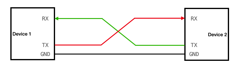
You don’t need to know the full specifics of UART to be able to work with it in our project. So I won’t explain the details here (although it is preferred if you know them). The main thing you need to know is that in UART, for the sender, they have something called a “Write wire”, usually labelled “tx”. And then the receiver usually has a “Read wire”, usually labelled “rx”.
Let’s say that the sender wishes to send some character to the receiver, in which case the sender’s tx wire is connected to the receiver’s rx wire. if the receiver also wishes to send any characters back to the sender, it must also have it’s own tx wire and the sender will need it’s own rx wire, both connected together.
 (click image to go to source)
The communication is digital, so the tx and rx wires have a zero or one being trasmitted, but both the devices need to agree on which voltage is considered zero. for that we have the GND (ground) pin of both the devices connected together.
Relevance
The reason we just discussed this is because this is going to be our primary mode of getting some sort of output from our RPi. Naturally the Operating System we are making is of no use if we cannot interact with it. We need to be able to somehow see what the OS is outputting (e.g. the stdout, printed statements, shell output, etc). The simplest way is to use a UART connection from the RPi to your host device (the system you’re using to make the OS). Therefore, the rest of this chapter will be dedicated to setting up the UART connection from the RPi to the host, and then implementing a basic “print” function which your OS can use to send a string to the host through the UART.
Hardware requirement
Do note, this will require some specific hardware. The tx and rx wires of the Raspberry Pi are actually pins, but your host system likely doesn’t even have pins or wires sticking out labelled “tx” or “rx”. So you will need something called a “TTL to USB connector” (TTL end being female and USB end being male). the USB will be able to connect to your host and the TTL will be able to connect to your RPi.
Now before you can begin coding, you actually need to setup the UART as well. By themselves the pins in the RPi do not work as UART tx/rx. You have to tell the RPi that they must serve as such.
RPi Boot Order
Before we can learn how to setup the RPi to employ UART, we need to understand some things about the RPi3b+. Firstly, look at your Raspberry Pi closely from top. near the center you will see a chip with the “BROADCOM” company label. That is the main processor of our RPi. But it’s not actually just a CPU, it’s something called a “System on Chip” (SoC). This little processor has our GPU, the CPU, Memory Controller, Timer controllers, other chips, and of course the UART controllers. The CPU which does the fetch execute cycle is also part of this SoC. To be accurate, there are CPU cores. the RPi has four CPU cores, that means four different separate portions of hardware that can do their own fetch execute cycle, with their own sets of interrupts, stack, registers, etc.
When you start your RPi, the first thing that is powered and runs is not actually any CPU core, but the GPU. This is a bit unusual from other computers. The GPU then starts the firmware and bootcode and sets up the hardware according to files like config.txt. Then, the kernel8.img is loaded to memory and only one of the four CPU cores is started which starts execution at address 0x80000. Other cores remain “parked” until we decide for them to start.
Now, remember that in previous chapter I suggested that you first flash some official RPi OS using the official imager, and then simply overwrite your kernel and config files to it. So you don’t have to setup most of the bootcode and firmware stuff. The only thing relevant is the config.txt file.
Memory Mapped IO
Now, only the CPU can actually execute instructions. It is the one who does everything once it starts. How does it configure and handle the other components in the SoC? Like the Timer controllers and UART controllers and such? The RPi follows something called “Memory Mapped IO”. So instead of having separate wires and connections going from the CPU to other components, the other components have some assigned “Memory Addresses”. The components write their current state to these memory addresses, the CPU can read them just like reading any other memory address, and then write data back which is read by the components. So each component has it’s own dedicated parts of main memory which only serves as communication between the components and the CPU.
Do note, of course we have multiple CPUs, multiple CPUs trying to talk to the same component can sometimes cause complications, but we’re not going to focus on multi-core system right now. Currently we will only work with one core working.
UART in RPi
The SoC in the RPi has two UART components. Labeled UART0 and UART1. UART0 is of type “PL011” (PL011 doesn’t mean anything here, it’s just a way to identify the type of UART). UART1 is a Mini UART, not PL011. For basics, you just need to know PL011 UARTs are more thorough UARTs with their own clocks, more configuration options, bigger transmittion limits, etc. Mini UART is very barebones. Tied to the GPU clock, lesser transmittion size, less featured, etc.
Now, it is our responsibility to tell the RPi that we wish to use a UART, and that we need to set one of the pins in our RPi to be tx and rx for the UART. Actually reading and writing can come later.
To enable UART, it is simple, you merely need to add the following in your config.txt
enable_uart=1
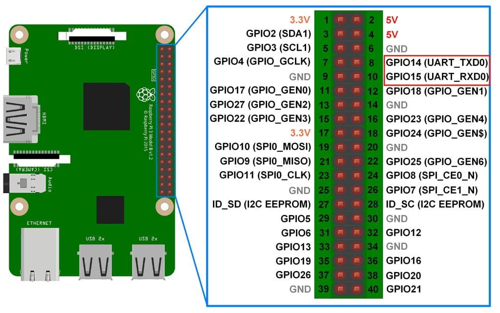
Now, when the RPi boots, and the GPU is setting up the system for the CPU, when it sees the config.txt it is going to start UART1, initialize it, and internally set it up so that the Pin number 8 labelled GPIO14 will act as the tx wire, and pin number 10 labelled GPIO15 will act as rx wire. and pin number 6 will act as the ground pin. Refer to the Pin diagram below.
 (click image to go to source)
Now, your CPU can simply communicate to UART1 what string it wishes to send to the host, by writing to the correct addresses for UART1. UART1 will correctly convert it to digital signals and send it to the correct pins. So the setup is technically complete on RPi side.
Something to note is that enabling UART also causes UART0 to be mapped to the bluetooth module of the RPi. We’re not going to discuss this for now.
UART on host machine
It’s actually pretty easy to setup on the host machine. You just need to install a tool which will manage UART for you. In this project I use minicom. It’s as simple as using an installation command. It differs based on your OS. You can refer to the your host system’s package distributor to get it. For me on Arch Linux it was:
sudo pacman -S minicom
Connection
Your TTL to USB cable will have four TTL. Connect the Green cable to rx (pin number 10, GPIO15), the White cable to tx (pin number 8, GPIO14), and the black cable to GND (pin number 6). Note that you also have a red cable. It carries a high 3.3V or 5V voltage depending on your host’s configuration. Either way you are NOT SUPPOSED TO CONNECT IT TO ANYTHING ON YOUR RASPBERRY PI. It will destroy your RPi, you do not need it for the UART to work. Just connect the three wires and USB to your host system.
Then, to start minicom. Run following immediately after connecting the USB to the laptop:
dmesg | tail
This will show you something like “xxxx converter connected to ttyUSBx”
Remember that last phrase. and use it in the following command:
sudo minicom -D /dev/ttyUSBx -b 115200
where you replace ttyUSBx with the last word in the previous command output.
Note the number in the end. That is the BAUD RATE of our UART communication. It basically means the rate at which the data will be transfered. You can find resources online to learn more about it. 115200 is the baudrate that the UART1 will be set to by default.
That’s all!!! Now anything your RPi outputs can be seen in your minicom window! you can close minicom whenever you’re done by: Ctrl+A, and then press X on keyboard.
Implementation
Finally, we can get to actually implementing the print function in our operating system!
If we go through the official documentation of our broadcom SoC
You can find under the “UART1” topic the relevant memory addresses that CPU can read and write from to manipulate the UART1 into doing what we want it to do.
All these addresses are called “Registers”. Note that these differ from the registers on our CPU. Unlike the CPU registers, these registers are physical tiny blocks of memory on the UART1. However the SoC maps these registers to the main memory addresses so our CPU can read and write to them.
In the official listing of the registers of UART1, you can see all of them have different tasks. Some of them can be written to for changing the BAUD rate, some are read only which you (your cpu) can read you check certain statuses. Some are for setting up the UART1. However our GPU already has set up most things while parsing the config.txt. So all you need to do is check if the UART1 is currently accepting bytes to send to TX wire (by checking bit 5 in the AUX_MU_LSR_REG register) and then just writing the byte you want to send, to the AUX_MU_IO_REG register. To read or write to these registers you simply read or write to their corrosponding memory addresses as mentioned in the official documentation. 0x7E215040 for AUX_MU_IO_REG and 0x7E215054 for AUX_MU_LSR_REG.
Here is how the implementation goes:
use core::{fmt::Write, ptr::{read_volatile, write_volatile}};

const MMIO_BASE: usize = 0x3F000000;
const AUX_BASE: usize = MMIO_BASE + 0x215000;
const AUX_MU_IO: usize = AUX_BASE + 0x40;
const AUX_MU_LSR: usize = AUX_BASE + 0x54;

pub struct Uart;

impl Uart {
    pub fn write_byte(&self, c: u8) {
        unsafe {
            while read_volatile(AUX_MU_LSR as *const u32) & 0x20 == 0 {}
            write_volatile(AUX_MU_IO as *mut u32, c as u32);
        }
    }
}

impl Write for Uart {
    fn write_str(&mut self, s: &str) -> core::fmt::Result {
        for b in s.bytes() {
            self.write_byte(b);
        }
        Ok(())
    }
}
now you can simply write a character to UART1 using
let uart = Uart;
uart.write_byte(b'A');
According to the documentation bit 5 in AUX_MU_LSR_REG is set to 1 when UART1 is able to accept a byte meant to be sent to TX. So in write_byte() we simply wait till the value of said register is of the form X1XXXXX and not X0XXXXX. And when it is the former, we know we can send a byte, which we do by writing to AUX_MU_IO_RED address. From their UART1 will send the bytes to the tx pin and thus to the host system, where you will be able to see it in your minicom window.
Traits in Rust
Note that other than just implementing the basic function write_byte, we also implemented something called “Write” for “Uart”. “Write” is actually something what’s called a “Trait” in Rust. Essentially, you must be familiar with object oriented programming. The child of a certain class inherits all the functions and features of the parent class. In a way, you end up with a system where you can create functions which only take objects which inherit from some parent class. Or you could create a child class which inherits from a parent class, so the child class has all the convenient methods and features of the parent class.
However in Rust we have a more flexible system for achieving something similar. Sometimes, maybe we have an object that already inherits from some other parent, and we cannot change who it inherits from for whatever reason. But we still want it to inherit methods and features from some useful class. That’s how traits function. In Rust instead of making a class be a child of some parent class, you have another option of inheritence, where you can implement a “Trait” to your class. For example if you implement a trait called “Write” for your class, suddenly your class will inherit all the useful features and methods involved in the “Write trait”. Suddenly you will unlock all the methods that come with the Write trait, all without having to change your class’s parent. This is very powerful and very useful.
In order to implement some trait in your Rust class/struct, you need to define some base foundation level methods or parameters that are needed for the trait to build upon and work. Some very rudimentary featurese that the trait itself will expect you to define for it to use. For the Write trait, such a thing is the “write_str” method. You must make it take in a reference to self, and then a &str argument, and it must return a core::fmt::Result datatype.
The advantage of implementing the Write trait to our Uart is suddenly you inlock the Uart.write_fmt method. This is useful in string formatting. Because the write_fmt method automatically handles string formatting.
println!
Technically you can already print things. E.g.
#![allow(unused)]
fn main() {
let mut uart = Uart;
uart.write_fmt(
    core::format_args!("x = {}", 42)
).unwrap();
}
However, this is quite ugly and I’d rather not type all that out everytime I wish to print something. Firstly let’s wrap this up in a clean little function called _print
#![allow(unused)]
fn main() {
pub fn _print(args: core::fmt::Arguments) -> core::fmt::Result {
    let mut uart = Uart;
    uart.write_fmt(args)?;
    Ok(())
}
}
Notice that if we wanted to use this, we would still need to type out something like
#![allow(unused)]
fn main() {
_print(core::format_args!("x = {}", 42));
}
to eliminate the core::format_args part, we can further wrap this function into a macro.
#![allow(unused)]
fn main() {
#[macro_export]
macro_rules! print {
    ($($arg:tt)*) => ({
        $crate::kernel::peripherals::_print(
            core::format_args!($($arg)*)
        )
    });
}
}
And that’s your print! macro! Take your time studying the syntax, but the main crux is that it takes all the arguments you write in print!(...) and calls the _print function with all your arguments wrapped up in the proper _print argument syntax.
And now, if instead of just passing format_args! to _print, if you wrap it into another format_args! with base string for formatting as {}\r\n, and THEN pass it to the function you get:
#![allow(unused)]
fn main() {
#[macro_export]
macro_rules! println {
    ($($args:tt)*) => ({
        $crate::kernel::peripherals::_print(
            core::format_args!("{}\r\n", core::format_args!($($args)*))
        )
    });
}
}
Which is our println!! You can now call this as simply:
#![allow(unused)]
fn main() {
println!("\r\nWelcome to, AtOS.").unwrap();
}
Now just ensure all this is in some file which is actually compiled by the Rust compiler, compile the project, build your kernel8.img, and write it to your RPi memory card. Then connect your UART cable as described and power on your RPi. And you’ll see your output!
Welcome to, AtOS.
Final codes
./kernel/peripherals.rs
#![allow(unused)]
fn main() {
use core::{fmt::Write, ptr::{read_volatile, write_volatile}};

const MMIO_BASE: usize = 0x3F000000;
const AUX_BASE: usize = MMIO_BASE + 0x215000;
const AUX_MU_IO: usize = AUX_BASE + 0x40;
const AUX_MU_LSR: usize = AUX_BASE + 0x54;

pub struct Uart;

impl Uart {
    pub fn write_byte(&self, c: u8) {
        unsafe {
            while read_volatile(AUX_MU_LSR as *const u32) & 0x20 == 0 {}
            write_volatile(AUX_MU_IO as *mut u32, c as u32);
        }
    }
}

impl Write for Uart {
    fn write_str(&mut self, s: &str) -> core::fmt::Result {
        for b in s.bytes() {
            self.write_byte(b);
        }
        Ok(())
    }
}

pub fn _print(args: core::fmt::Arguments) -> core::fmt::Result {
    let mut uart = Uart;
    uart.write_fmt(args)?;
    Ok(())
}

#[macro_export]
macro_rules! print {
    ($($arg:tt)*) => ({
        $crate::kernel::peripherals::_print(
            core::format_args!($($arg)*)
        )
    });
}

#[macro_export]
macro_rules! println {
    ($($args:tt)*) => ({
        $crate::kernel::peripherals::_print(
            core::format_args!("{}\r\n", core::format_args!($($args)*))
        )
    });
}
}
./kernel/mod.rs
#![allow(unused)]
fn main() {
pub mod peripherals;
}
main.rs
#![no_std]
#![no_main]

mod kernel;

use core::panic::PanicInfo;

#[no_mangle]
pub extern "C" fn main() -> ! {
    println!("\r\nWelcome to, AtOS.").unwrap();
    loop {}
}

#[panic_handler]
fn panic(_info: &PanicInfo) -> ! {
    println!("Some exception happened!").unwrap();
    loop {}
}
The next repository state snapshot link will be provided at the end of chapter 5.