Welcome
RustOSGuideforRPi3
This is a chapter wise beginner friendly guide to creating an Operating System for the Raspberry Pi 3 board, from scratch. This is written by me as I work on my own OS in the same condition. It serves as both as an educational guide and also a documentation of how I myself made my own OS. Naturally this means it is possible that as I discover more information, I may have to heavily amend previous writings. But still, I think it will be greatly beneficial to beginners who don’t know anything.
Structure
The structure is extremely simple. The chapters follow a journey like chronological order. Instead of explaining one aspect at a time, they are meant to be followed through in an episodic format. Meant to cover implementations the same order as the order in which a real developer would tackle them in his project. However this continuity starts from Chapter 1. Chapter 0 is more akin to rough a prologue chapter for people who have absolutely minimal knowledge about the subject.
Contribution
This guide is still incomplete so the final proof reading and correction is yet to be done. However, no pull requests will ever be accepted, not right now, neither after this guide is complete. Issues however can be freely opened about mistakes, suggestions, recommendations, etc.
AtOS
My operating system which this entire guide is technically a documentation of, is named “AtOS”. All the source code is pubicly available in the below linked repository. Chapters may also link to its old snapshots for reference. While this book does not accept pull requests, AtOS accepts any reasonable contributions to it. However AtOS is not meant to be a large scope operating system. It is only meant to serve as the foundation for this guide, so adding complicated features which are not covered by this guide will not be accepted.
Links
- Free online book version: zackygamedev.github.io/RustOSGuideforRPi3
- Source Repository: github.com/ZackyGameDev/RustOSGuideforRPi3
- AtOS source code: github.com/ZackyGameDev/AtOS/
Chapter 0: Basic Information
Creating an Operating System from scratch is widely considered to be one of the most challenging tasks in computer science. It involves getting to know your machine at a hardware chip level, and getting acquianted with features and quirks that you never would have to worry about at software level. However it is still an attractive challenge because creating an Operating System can reward you with knowledge and insights of Computer Science at a personal level. Regardless whether you’re doing this out of passion, out of need, or just because you’re curious about how this all works. The point of this guide is to walk you through all the concepts involved from a beginner stage. This chapter will involve all the knowledge you need to have before you can write your first line of code.
Where I come from
I am not a professional Operating Systems Engineer, nor am I a professor with lots of knowledge in this field. I just happen to be working on my own OS and I think I could do a helpful job of documenting the entire process. Naturally this means if I learn new things, I may edit chapters to add things to them or fix them. I can’t promise that writing this guide will remain my top priority. However, I intend to fully follow through with it alongside my OS development.
Targetted Hardware
This guide will specifically tailor to the Raspberry Pi 3 board. I myself used the RPi3b+ for my project, but everything should work for all interations of RPi3. From the start, the primary way of receiving output from our code running on the RPi will be through something called “UART” (discussed later on), which will require a TTL(female) to USB(male) cable. And of course I’ll assume you have a power supply for your RPi as well.
Project boundaries
Like I mentioned, the purpose of this entire documentation is strictly RPi3 OS development, that means it’s possible that things you learn through this document may not necessarily apply on other hardwares. Any description of hardware behaviour should be assumed to be written with RPi3 in mind specifically. Though, RPi3 is not an entirely strange or alien machine, it also follows most standards that many other computers do, so knowledge is not exactly wasted if your ultimate target is a different hardware.
That wraps up the personal statements.
Fetch-execution cycle
When writing something that will run directly on the computer chip, without any underlying operating system, it is the most foundational step that you know exactly how your code actually looks like while it is being run by the computer chip.
A bit about working memory
You must know what “RAM” is, its a piece of memory that your computer uses for random access of data and code. The CPU chip will always run code directly from the RAM. The way it works is that RAM, to the computer, is pretty much just a ridiculously long array of bytes. Where all the bytes are indexed from zero to… wherever the last byte is. Since there’s so many of these, we will always use hexadecimal notation when referring to the index of any of these bytes. (To signal that the number written is supposed to be hex notation, it will be prefixed by 0x which is also the standard used in most programming languages.)
The index of these bytes is called the “address” of this byte, and the byte itself, is called the “data”.
So if somebody asks “what is the data at address 0x5fff” they’re really just asking for the byte with the index “0x5fff” (which is just 24575 in decimal)
Note: whenever this guide mentions “memory” without additional context, assume that it is referring to the RAM. The ROM, like your SSDs or HDDs are usually called “disk”. In our context, our “disk” is going to be the microSD card that we put our operating system data on before plugging it into the pi.
What does your code actually look like?
You need to know that the CPU chip itself is basically just a really, ridiculously complicated electrical circuit. It isn’t really “intelligent” and it doesn’t exactly “know” things. It simply reads data from addresses, and depending on what that data is, some electrical circuit behaviour is triggered inside it, and then optionally it might also write data back to some memory address.
Now, as for your code. When you compile your code, it basically gets converted into something called “Machine language”. Which is a format that the CPU can actually understand. Something that if the CPU reads bytes from, it will trigger the correct electronic circuitries inside it for it to produce the behaviour that the code wanted.
Machine code is also just a series/array of bytes. The files that you run can have many sections in them, but in all of them there is a section for such bytes which do not represent any data, instead, they are supposed to be read by the CPU to trigger the correct behaviours from it. These bytes are called “Instructions”
Now, I grossly oversimplified it, it is not so simple that if your instructions section has 10 bytes in an array, every byte individually represents a single instructions. It really does depend on which hardware you are talking about. But in the RPi3, every four bytes represent a whole instruction. so in memory, the code is stored as an array of bytes. And picking four bytes at a time, all of them are an instruction individually. You don’t really need to know the details of how to figure out from four bytes, which instruction it is. That’s the job of the CPU chip.
Fetch-execute cycle
Now, when the Raspberry Pi 3 starts, what it does is that it loads some data you give it through its memory card. That is, it literally copies the bytes from the memory card, directly to the RAM, in the exact order written on the card. Which sections from the microSD card are copied to what section of the memory will be decided and prescribed to the RPi by you (at least, after you learn how to; by reading further chapters). It then tries to read data at the address 0x80000. It assumes that the four bytes starting from 0x80000 represent an instruction. And then the CPU starts its job, it reads those four bytes from the memory at 0x80000, 0x80001, 0x80002, 0x80003, and then accordingly its internal circuitary behaves; the way it is designed to behave upon seeing that instruction (i.e. that exact order of four bytes). This is called “executing the instruciton”. If that behaviour involves writing some data to the memory, it does that, and then moves on to the next four bytes starting from 0x80004. Reading them, letting the circuitary inside it interpret them and behave to them, i.e. executing them, and then again moves on to next four bytes. This cycle goes on infinitely (ideally).
This is called the “Fetch execute cycle”. Because the CPU is in a never ending labour of fetching an instruction, executing it, and then moving on to next instruction in memory to do it all over again.
Do note, there are some instructions that make the CPU go to a different location in memory for the next instruction, instead of the instruction right next to the current one. These are called “Jumping” or “Branching” instructions. More on them will be discussed as needed.
Another note, the fact that the RPi3 starts executing instructions from 0x80000 instruction is completely fixed. It is just the way its processor is designed. As a systems programmer, you will encounter many design choices like these from the manufacturers of your hardware. You will just have to figure out how to deal with it and work with what there is.
Registers x0-x30 and Stack Pointer
TODO — low priority
You can probably find resources to explain this easily.
But for example:
www.geeksforgeeks.org/computer-organization-architecture/different-classes-of-cpu-registers/
dev.to/serputov/aarch64-x86-64-registers-and-instruction-quick-start-19bd
en.wikipedia.org/wiki/Stack-based_memory_allocation
Chapter 1: Baremetal Rust
Now that you know exactly how code is actually run and what it looks like after compilation, we have to actually make it run. We are trying to write an Operating System in rust. So of course we need to figure out how to make program written in rust run directly on our RPi without any underlying operating systems.
Project init
NOTE: This section is for Linux (where you’ll write your rust code and compile it for the Pi). If you’re using a different OS some things may or may not be different. Feel free to take help from LLMs or other online resources for setting up your baremetal rust project with aarch64-unknown-none as your target.
Let’s first initialize our bare bones project. But before we do that we need to run:
rustup target add aarch64-unknown-none
This will install and add whatever Rust compiler needs to be able to compile code to instructions that can run on “AArch64” architecture (basically RPi3’s CPU architecture). The “unknown” and “none” refer to the “vendor” and “underlying operating system” of your target respectively.
Now you can initialize your project with cargo. (comes with rust)
cargo new atos --bin
cd atos
Now in your project folder there must be a file named “Cargo.toml”. You can add some basic information about your project there. For me it was:
[package]
name = "at-os"
version = "0.1.0"
authors = ["ZackyGameDev <zaacky2456@gmail.com>"]
Next, we have to tell our project what our rust code is meant to be compiled for. Create a file .cargo/config.toml which will have information about our compiling settings. and put the following in it:
[build]
target = "aarch64-unknown-none"
Optionally, if you’re using vscode then tell the linter/syntax checker what you’re targetting by putting the following in .vscode/settings.json:
{
    "rust-analyzer.check.allTargets": false,
    "rust-analyzer.cargo.target": "aarch64-unknown-none"
}
Now there’s still some more we have to setup before we can actually build it, but before that we have to understand some more things and write a little bit of code.
Lack of Underlying OS
In rust, and in pretty much any programming language actually, there are many features that rely on Operating Systems beneath them, for them to work. For example in C, when you want to open a file, the instructions from your compiled C code itself don’t really read the disk directly trying to decipher the data on the disk to find your file and start writing to it. Instead, your code will ask the Operating System beneath to do it for you, and just give you something like a pointer to the file. This is usually so programs written don’t need to access the memory directly (becaues if they’re evil or terrible they might try to mess up with parts of memory you wouldn’t want them to mess up).
If you’ve read up on this, you’d know this way of asking the operating system for something is called “System Calls”. Where essentially the programming language (in user space) is relying on the kernel (in kernel space) to provide low level interactions through system calls. (read about it at OSTEP: Ch6)
Well what about when you’re running your code directly on the computer without any operating system beneath? What if there’s no “kernel” to do system calls to? It’s simple. Those features become unusable and pretty much useless. And in rust, “those features” includes the entire Rust Standard Library called std.
Lack of crt0
Rust code, normally on windows or linux just running normally on the same machine, doesn’t run directly. What happens under the hood is that first, something called the “C Runtime Library” is run. What it does is basically setup the environment and parameters of the hardware, in preparation for Rust code to run. It first does something called “setting up the stack” and “initializing .data” or “zeroing the .bss” (we’ll learn what it is later). And then it literally calls the function named “main” in your rust code. (Which is why the first lines of code to run are written in a function called “main()”, because that’s the name crt0 calls).
As you may have guessed, when making our rust on baremetal, there is no such thing. The labour of “setting up stack” or preparing environment for rust is also going to be need to be done by you manually, before your rust code even starts. But wait… if we have to write some code that does some stuff before Rust code can run… that means that preparation code can’t be written in Rust… The truth is unavoidably, we’ll have to write this preparatory code in assembly. Because it’s pretty much the only language that can run immediately without any preparation (because you’re literally writing the structure of the machine code directly). Although you can try to minimize it as much as possible, in this entire project you’ll have to unavoidably write some bits in assembly
Assembly entry point and preparing for Rust main
Time to finally write those first ever lines of code that will run at 0x80000 (I hope you know the relevance of this address by now).
You can put your file anywhere, for me I put it at root of the project, ./entry.S. This is what it looks like:
.section ".text.boot"
.global _start

_start:
    // set stack pointer
    ldr   x0, =_stack_top
    mov   sp, x0

    // jump to rust
    bl   main

1:
    wfe
    b 1b
If you’ve never used assembly before, this might look scary, but it’s pretty simple. Let’s understand this line by line. The first line defines the section this code will go to (discussed under linking further below). Then .global _start just means “this symbol called _start should be accessible globally, to all files and codes”. This is just for the linking discussed further below.
Next, the first lines of code (labeled under _start). All we’re doing is loading up an address _stack_top in the x0 register of the chip, and then copying that value to the sp register from x0 register. We load it into x0 first because there’s no instruction to copy an address directly to sp register.
(If this seems alien, refer to chapter 0 about registers and stack)
ldr, mov and bl are all instructions. There’s probably uncountable instructions on the ARM chip. But you can google for them as you need them. Writing assembly literally just involves listing all the instructions that need to be run line by line. Sometimes those instructions might need some more specification like “which register is this instruction going to copy value to?” or “what value is this instruction dealing with?”. Those are written after the instruction name, separated by commas. every line of instruction is just “INSTRUCTION ARG0, ARG1”.
And then finally we do bl main which literally just means “call the code under the label main”. Where is main you ask? Well.. that’s the main function in our rust code of course! So what this is essentially doing is calling the rust main function after setting the sp register to some value.
You might’ve noticed we just pulled this variable called _stack_top and just assumed it has the correct address to set the stack to. But where was this defined? Where did it come from? Well again, it is defined in the linking process. Assembly doesn’t really have variables. It’s not like there’s some variable defined on the stack or heap which the assembly accesses like other programming langauges. If it worked like that we would’ve written the instructions to access data from the heap and use it. This is actually something called a “symbol”. kind of like inline macros from C. The linker while producing the final output file will see this symbol, and try to find where that symbol is defined. And then everywhere in code it will replace the symbol with its correct defined value.
In any case, as it turns out setting sp register to the correct value happens to be pretty much all you need to do to call your main funciton in rust and expect it to work correctly. So that’s what we do. The way the bl instruction works is that once the rust main function finishes executing, it’s going to come back to this assembly code and resume executing the instructions written after the bl instruction. But Operating Systems don’t really finish executing. They continuously in an infinite loop manage the hardware, respond to user, and facilitate services for softwares running on it. So that’s what the last few lines are for. It’s pretty much just an infinite loop which tells it to wait for a bit wfe, and then jump back to label “1”. Hopefully these instructions will never be executed because our rust main function will never return. But it is still there as a fail safe.
Rust main.rs
Finally, we can write some Rust code.
There must be a file src/main.rs in your project created automatically. It houses our main function.
Earlier we discussed that the standard library will not function in our project. Therefore we disable it by writing #![no_std] at the top of main.rs.
Also, since we do not have crt0, we also have to tell rust to NOT generate anything for it, and not expect the C Runtime Library to be there to run the main function automatically. For this you put #![no_main] at the top of your file.
Next our actual main function!
#[no_mangle]
pub extern "C" fn main() -> ! {
    loop {}
}
We use extern "C" to let it know that this function must follow C-style convention for being called. The C-style convention basically decides how can code written in assembly call this function by trying to jump to it as a label with instructions like bl. It is important because this is how our bl main line in entry.S will actually work.
Also, when the compiler compiles our code, it may obfuscate or change our function’s name to some random garble to make it unique and save space. But we don’t want that. We want the function name to stay the same after compilation, so our entry.S and other files can recognize it with the symbol main. For that we put #[no_mangle] before the definition.
as for the return type, ! just means that this function should NEVER return. That means it will never ever finish executing (through an infinite loop).
Panic handling
Now, if you try to do something illegal in rust, which raises an exception. Or in Rust lingo, causes your program to panic, Rust usually prints out a very helpful message to stdout to tell you where your code messed up. It also shows a very generous option to see a backtrace to exactly which function called which function to lead to the line at which the error happened. Sadly, all this functionality is defined in std. Which we have excluded. So now we are left to implement that panic handling ourselves.
It is actually very simple. You just need to write a function that accepts a core::panic::PanicInfo object, and just mark it as the “panic handler”. Like so:
#![allow(unused)]
fn main() {
use core::panic::PanicInfo;
#[panic_handler]
fn panic(_: &PanicInfo) -> ! {
    loop {}
}
}
Whenever a panic occurs, this function will be called. And you can access panic information from the one argument. We can implement panic handling later. For now we’re just trying to appease Rust compiler. So all our handler does right now is enter an infinite loop upon panic.
Now Rust will no longer complain about no panic handler being implemented.
Another thing is that when a panic happens, rust uses something called “unwinding”. Which basically frees up memory in the event a panic happens. And gracefully exits out to the parent who called the panic inducing function/thread. However, unwinding uses some OS specific libraries which we obviously do not have. Therefore, we are going to disable this feature as well to avoid unpredictable behaviour.
For this just append the following .cargo/config.toml:
#![allow(unused)]
fn main() {
[profile.dev]
panic = "abort"

[profile.release]
panic = "abort"
}
This is going to change the behaviour on panic, from unwind to abort. So Rust will not try to do any additional behaviour upon panic, it will simply call our panic handler and pass it a PanicInfo object. No unwinding will be attempted.
Now this wraps up our Rust code.
Final version of all code files are available at the end of this chapter.
Linking
Finally the part where we start putting together all our project to compile, build and produce a single file to give to the RPi.
In chapter 0 I mentioned that you will be able to tell RPi, which memory addresses to put what code or what data in when booting it. The way it works is the following: When you compile your code (by using the build commands we will talk about in a bit), all the files in your code are first compiled, i.e. translated to machine code. Then something called the “Linker” combines all those machine codes into a single file. Which we give to our raspberry pi; to copy to the memory after booting. Now RPi will always just copy the entire file exactly one to one to it’s memory. so data from addres 0x00000 in the file will be copied to the address 0x80000 in the memory and so on. So to decide what data goes to which memory, you have to put it at the correct place in the compiled file itself.
Since it is the Linker who combines all the code into a single file, it also provides us the option to let it know which code can be expected to go to which addresses when the final compiled file will run. This is done through something called a “Linker script”. To be exact, we’re going to give a “label” to our code which we want to run immediately after RPi boots. And tell the linker to put all the code with that label at the address “0x80000”. (Because as discussed last chapter, that is the hard fixed address that RPi starts executing instructions from after booting).
To be exact, when we say we tell the linker to put all the code at address 0x80000, it doesn’t mean that the data will start at that address inside the file. No in fact, it means that when this code is running, it can be expected to reside in the address 0x80000 in memory. So all the instruction bytes in our final file will expect other data to be found in the addresses specified by linker.
The linker, and in general our cargo build command will actually produce something called an “ELF” file (stands for executable and linkable format). It is basically the format of .exe files followed by Unix systems (including linux). You can read about them more, but mainly what you need to know is that ELF files are meant to be run, so they have an entry point, and some additional information about them in the first couple bytes called “header”. But what our RPi expects is literally just a snapshot or “image” of what the RAM should look like. That file is called “kernel8.img” (this filename is fixed, RPi will look for this exact file name). RPi just loads this file as is to memory.
So we will first use cargo with our linker script to produce an ELF file, and then convert it to a kernel8.img file for RPi. and that img file is what goes to the memory card.
We’re going to define the linker script in the root of the directory. Though you can put it anywhere.
linker.ld
ENTRY(_start)

SECTIONS
{
    . = 0x80000;

    .text :
    {
        *(.text.boot)
        *(.text*)
    }

    .rodata : { *(.rodata*) }
    .data   : { *(.data*) }
    .bss    : { *(.bss*) }

    . = ALIGN(16);
    _stack_top = . + 0x4000;
}
Okay now we have to understand this.
The first thing you need to tell the linker is the entry point of your file. If you remember we made our label _start global in entry.S. The entry point defined here is irrelevant to Raspberry Pi, it will just run instructions from 0x80000. But you need to define it anyway for the intermediate ELF file to be generated.
Next, we define our sections, where we actually tell it what to put where in memory.
. is a pointer, Kind if like how you have a cursor in text editing programs. When you type text, it moves ahead. And you first place your cursor to the location you want to start typing from. The same way we first do, . = 0x80000. Which means placing the cusor at 0x80000 location to start writing from there. This address is the place execution starts from in RPi.
Then first section is .text which stands for “code”. It’s a very strange naming choice, but yes, sections of bytes meant to be executed as instructions are typically called as “text” in low level memory.
For .text, we can define what the section should actually look like. Since we want the subsection we wrote .text.boot to be at 0x80000, it should come first. Hence, we put .text.boot first and then .text* which means all remaining other instructions. After that the rest of the sections. .rodata is read only data. Values of constants defined in code, or read only strings, or string literals. Then .data is for variables which are initialized in the code. They are writable and mutable. Finally .bss is data initialized to be zero in the code, also writable.
You may have noticed we did not define sections .text, .data, .rodata and .bss ourselves. They’re actually default conventional names that the compiler generates. We’re just telling the linker where to put them. The only thing we defined ourselves was the subsection for .text called .text.boot.
Now, remember, the . is a pointer, like a cursor. So now that we’ve put a bunch of sections, it must’ve moved to hold an address at the end of the last section we put. We now do . = ALIGN(16);. What it does is that– if the address that the pointer is currently at, is not divisible by 16, it will increment it till it is divisible by 16. And then we finally define the symbol _stack_top to be the final position of the pointer (aligned to 16 divisibility), plus, 0x4000. That means when we set sp to _stack_top in entry.S, it is going to have 0x4000 size of address space avaiable to it from _stack_top - 0x4000 -> _stack_top.
If this seems alien or strange, please lookup what a “stack” is in memory.
Note: We align to 16 because in AArch64 standard, stack pointer is always expected to be 16 aligned whenever a function is called. That is, every stack entry address should be a multiple of 16.
Finally, we have completed all the code we had to write. We can now build it
Building
It is recommended to first use a tool like “Raspberry pi imager” to first flash any OS in the memory card. It sets up the memory card’s partitions and file systems so we just have to copy paste our image.
Now, you have to tell your rust script that it needs to follow our linker.ld script. Otherwise it will ignore it. Do so by adding the following to .cargo/config.toml
[target.aarch64-unknown-none]
linker = "aarch64-linux-gnu-ld"
rustflags = [
  "-C", "link-arg=-Tlinker.ld",
]
Next, we need to setup something that will compile our assembly files. For that create a file named “build.rs” in root directory. By convention cargo runs this file first if it sees it. Before doing rest of the compilation. We’ll tell our build.rs to compile our assembly files:
fn main() {
    println!("cargo:rerun-if-changed=src/entry.S");

    cc::Build::new()
        .file("src/entry.S")
        .flag("-c")
        .compile("entry");
}
As you can see, it needs a dependency called “CC” which stands for “cargo C”. It’s a dependency that helps compile C files or Assembly files for your project. Add the following to your cargo.toml.
[dependencies]

[build-dependencies]
cc = "1.0"
Finally, the moment of truth, use the following command to get the ELF file compiled:
cargo build --release
This will give you an output at target/aarch64-unknown-none/release/<your_binary_name>.
Now to convert this ELF file to raw binary image for the RPi, we use:
aarch64-linux-gnu-objcopy \
target/aarch64-unknown-none/release/<your_binary_name>\
-O binary kernel8.img
Where <your_binary_name> depends on your create name by default.
Now you have a kernel8.img that you can just copy to your RPi!
Create one more additional file named config.txt and put this:
arm_64bit=1
enable_uart=1
Finally, after you’ve used the Raspberry Pi Imager tool to flash any random OS to your memory card, you can just open the files in your memory card, open the bootfs partition and copy paste the files “config.txt” and “kernel8.img” from your project directory to this bootfs partition.
Any time you make a change to your code, just do cargo clean before running the two commands again. And you just have to overwrite the old kernel8.img with the new one everytime. And just plug it to the Pi and power it up!
Final codes
main.rs
#![no_std]
#![no_main]

use core::panic::PanicInfo;

#[no_mangle]
pub extern "C" fn main() -> ! {
    loop {}
}

#[panic_handler]
fn panic(_info: &PanicInfo) -> ! {
    loop {}
}
.cargo/config.toml
[build]
target = "aarch64-unknown-none"

[target.aarch64-unknown-none]
linker = "aarch64-linux-gnu-ld"
rustflags = [
  "-C", "link-arg=-Tlinker.ld",
]

[profile.dev]
panic = "abort"

[profile.release]
panic = "abort"
The rest of the files you can find an identical version at github.com/ZackyGameDev/AtOS/tree/81fcfb3cbdbd0fb0add78b5c89ff8e5bad70d260 (Do note, the naming may differ, also main.rs is different at this commit, please ignore it.)
Other readings
os.phil-opp.com/freestanding-rust-binary/ Excellent blog, though it is targetted for a different hardware, it is still an amazing read that covers a lot more.
Chapter 2: Serial Output
Imagine you had the task of sending some data, specifically, a string of characters over a wire. How would you achieve it? You would have to create a system where the characters can be expressed in the form of electronic signals and then create some standard to transmit those signals to the other person, and some standard for that other person to be able to interpret those signals back to the characters they are supposed to be.
This is a classic electronics problem, with many solutions. But one of the most common standards is the Universal Asynchronous Receiver/Transmitter, UART for short.
UART
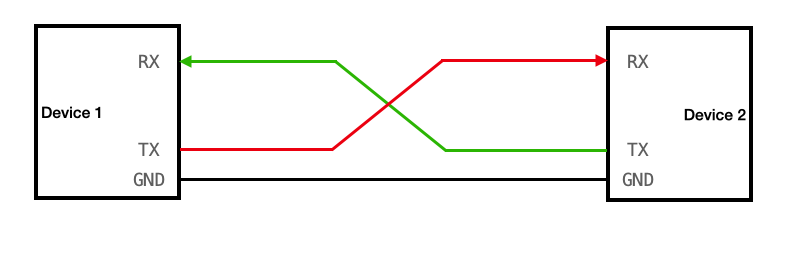
You don’t need to know the full specifics of UART to be able to work with it in our project. So I won’t explain the details here (although it is preferred if you know them). The main thing you need to know is that in UART, for the sender, they have something called a “Write wire”, usually labelled “tx”. And then the receiver usually has a “Read wire”, usually labelled “rx”.
Let’s say that the sender wishes to send some character to the receiver, in which case the sender’s tx wire is connected to the receiver’s rx wire. if the receiver also wishes to send any characters back to the sender, it must also have it’s own tx wire and the sender will need it’s own rx wire, both connected together.
 (click image to go to source)
The communication is digital, so the tx and rx wires have a zero or one being trasmitted, but both the devices need to agree on which voltage is considered zero. for that we have the GND (ground) pin of both the devices connected together.
Relevance
The reason we just discussed this is because this is going to be our primary mode of getting some sort of output from our RPi. Naturally the Operating System we are making is of no use if we cannot interact with it. We need to be able to somehow see what the OS is outputting (e.g. the stdout, printed statements, shell output, etc). The simplest way is to use a UART connection from the RPi to your host device (the system you’re using to make the OS). Therefore, the rest of this chapter will be dedicated to setting up the UART connection from the RPi to the host, and then implementing a basic “print” function which your OS can use to send a string to the host through the UART.
Hardware requirement
Do note, this will require some specific hardware. The tx and rx wires of the Raspberry Pi are actually pins, but your host system likely doesn’t even have pins or wires sticking out labelled “tx” or “rx”. So you will need something called a “TTL to USB connector” (TTL end being female and USB end being male). the USB will be able to connect to your host and the TTL will be able to connect to your RPi.
Now before you can begin coding, you actually need to setup the UART as well. By themselves the pins in the RPi do not work as UART tx/rx. You have to tell the RPi that they must serve as such.
RPi Boot Order
Before we can learn how to setup the RPi to employ UART, we need to understand some things about the RPi3b+. Firstly, look at your Raspberry Pi closely from top. near the center you will see a chip with the “BROADCOM” company label. That is the main processor of our RPi. But it’s not actually just a CPU, it’s something called a “System on Chip” (SoC). This little processor has our GPU, the CPU, Memory Controller, Timer controllers, other chips, and of course the UART controllers. The CPU which does the fetch execute cycle is also part of this SoC. To be accurate, there are CPU cores. the RPi has four CPU cores, that means four different separate portions of hardware that can do their own fetch execute cycle, with their own sets of interrupts, stack, registers, etc.
When you start your RPi, the first thing that is powered and runs is not actually any CPU core, but the GPU. This is a bit unusual from other computers. The GPU then starts the firmware and bootcode and sets up the hardware according to files like config.txt. Then, the kernel8.img is loaded to memory and only one of the four CPU cores is started which starts execution at address 0x80000. Other cores remain “parked” until we decide for them to start.
Now, remember that in previous chapter I suggested that you first flash some official RPi OS using the official imager, and then simply overwrite your kernel and config files to it. So you don’t have to setup most of the bootcode and firmware stuff. The only thing relevant is the config.txt file.
Memory Mapped IO
Now, only the CPU can actually execute instructions. It is the one who does everything once it starts. How does it configure and handle the other components in the SoC? Like the Timer controllers and UART controllers and such? The RPi follows something called “Memory Mapped IO”. So instead of having separate wires and connections going from the CPU to other components, the other components have some assigned “Memory Addresses”. The components write their current state to these memory addresses, the CPU can read them just like reading any other memory address, and then write data back which is read by the components. So each component has it’s own dedicated parts of main memory which only serves as communication between the components and the CPU.
Do note, of course we have multiple CPUs, multiple CPUs trying to talk to the same component can sometimes cause complications, but we’re not going to focus on multi-core system right now. Currently we will only work with one core working.
UART in RPi
The SoC in the RPi has two UART components. Labeled UART0 and UART1. UART0 is of type “PL011” (PL011 doesn’t mean anything here, it’s just a way to identify the type of UART). UART1 is a Mini UART, not PL011. For basics, you just need to know PL011 UARTs are more thorough UARTs with their own clocks, more configuration options, bigger transmittion limits, etc. Mini UART is very barebones. Tied to the GPU clock, lesser transmittion size, less featured, etc.
Now, it is our responsibility to tell the RPi that we wish to use a UART, and that we need to set one of the pins in our RPi to be tx and rx for the UART. Actually reading and writing can come later.
To enable UART, it is simple, you merely need to add the following in your config.txt
enable_uart=1
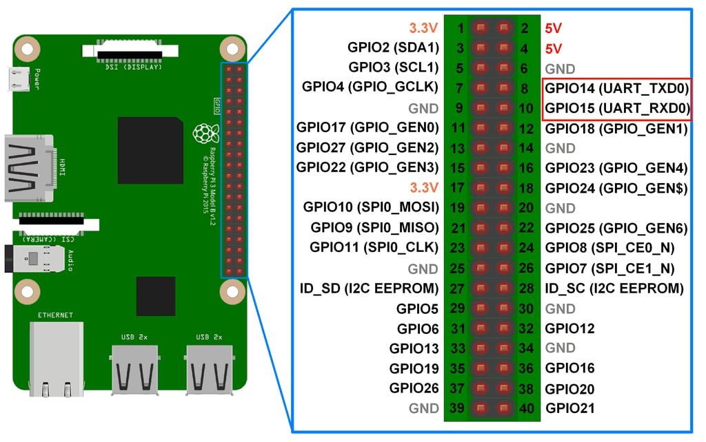
Now, when the RPi boots, and the GPU is setting up the system for the CPU, when it sees the config.txt it is going to start UART1, initialize it, and internally set it up so that the Pin number 8 labelled GPIO14 will act as the tx wire, and pin number 10 labelled GPIO15 will act as rx wire. and pin number 6 will act as the ground pin. Refer to the Pin diagram below.
 (click image to go to source)
Now, your CPU can simply communicate to UART1 what string it wishes to send to the host, by writing to the correct addresses for UART1. UART1 will correctly convert it to digital signals and send it to the correct pins. So the setup is technically complete on RPi side.
Something to note is that enabling UART also causes UART0 to be mapped to the bluetooth module of the RPi. We’re not going to discuss this for now.
UART on host machine
It’s actually pretty easy to setup on the host machine. You just need to install a tool which will manage UART for you. In this project I use minicom. It’s as simple as using an installation command. It differs based on your OS. You can refer to the your host system’s package distributor to get it. For me on Arch Linux it was:
sudo pacman -S minicom
Connection
Your TTL to USB cable will have four TTL. Connect the Green cable to rx (pin number 10, GPIO15), the White cable to tx (pin number 8, GPIO14), and the black cable to GND (pin number 6). Note that you also have a red cable. It carries a high 3.3V or 5V voltage depending on your host’s configuration. Either way you are NOT SUPPOSED TO CONNECT IT TO ANYTHING ON YOUR RASPBERRY PI. It will destroy your RPi, you do not need it for the UART to work. Just connect the three wires and USB to your host system.
Then, to start minicom. Run following immediately after connecting the USB to the laptop:
dmesg | tail
This will show you something like “xxxx converter connected to ttyUSBx”
Remember that last phrase. and use it in the following command:
sudo minicom -D /dev/ttyUSBx -b 115200
where you replace ttyUSBx with the last word in the previous command output.
Note the number in the end. That is the BAUD RATE of our UART communication. It basically means the rate at which the data will be transfered. You can find resources online to learn more about it. 115200 is the baudrate that the UART1 will be set to by default.
That’s all!!! Now anything your RPi outputs can be seen in your minicom window! you can close minicom whenever you’re done by: Ctrl+A, and then press X on keyboard.
Implementation
Finally, we can get to actually implementing the print function in our operating system!
If we go through the official documentation of our broadcom SoC
You can find under the “UART1” topic the relevant memory addresses that CPU can read and write from to manipulate the UART1 into doing what we want it to do.
All these addresses are called “Registers”. Note that these differ from the registers on our CPU. Unlike the CPU registers, these registers are physical tiny blocks of memory on the UART1. However the SoC maps these registers to the main memory addresses so our CPU can read and write to them.
In the official listing of the registers of UART1, you can see all of them have different tasks. Some of them can be written to for changing the BAUD rate, some are read only which you (your cpu) can read you check certain statuses. Some are for setting up the UART1. However our GPU already has set up most things while parsing the config.txt. So all you need to do is check if the UART1 is currently accepting bytes to send to TX wire (by checking bit 5 in the AUX_MU_LSR_REG register) and then just writing the byte you want to send, to the AUX_MU_IO_REG register. To read or write to these registers you simply read or write to their corrosponding memory addresses as mentioned in the official documentation. 0x7E215040 for AUX_MU_IO_REG and 0x7E215054 for AUX_MU_LSR_REG.
Here is how the implementation goes:
use core::{fmt::Write, ptr::{read_volatile, write_volatile}};

const MMIO_BASE: usize = 0x3F000000;
const AUX_BASE: usize = MMIO_BASE + 0x215000;
const AUX_MU_IO: usize = AUX_BASE + 0x40;
const AUX_MU_LSR: usize = AUX_BASE + 0x54;

pub struct Uart;

impl Uart {
    pub fn write_byte(&self, c: u8) {
        unsafe {
            while read_volatile(AUX_MU_LSR as *const u32) & 0x20 == 0 {}
            write_volatile(AUX_MU_IO as *mut u32, c as u32);
        }
    }
}

impl Write for Uart {
    fn write_str(&mut self, s: &str) -> core::fmt::Result {
        for b in s.bytes() {
            self.write_byte(b);
        }
        Ok(())
    }
}
now you can simply write a character to UART1 using
let uart = Uart;
uart.write_byte(b'A');
According to the documentation bit 5 in AUX_MU_LSR_REG is set to 1 when UART1 is able to accept a byte meant to be sent to TX. So in write_byte() we simply wait till the value of said register is of the form X1XXXXX and not X0XXXXX. And when it is the former, we know we can send a byte, which we do by writing to AUX_MU_IO_RED address. From their UART1 will send the bytes to the tx pin and thus to the host system, where you will be able to see it in your minicom window.
Traits in Rust
Note that other than just implementing the basic function write_byte, we also implemented something called “Write” for “Uart”. “Write” is actually something what’s called a “Trait” in Rust. Essentially, you must be familiar with object oriented programming. The child of a certain class inherits all the functions and features of the parent class. In a way, you end up with a system where you can create functions which only take objects which inherit from some parent class. Or you could create a child class which inherits from a parent class, so the child class has all the convenient methods and features of the parent class.
However in Rust we have a more flexible system for achieving something similar. Sometimes, maybe we have an object that already inherits from some other parent, and we cannot change who it inherits from for whatever reason. But we still want it to inherit methods and features from some useful class. That’s how traits function. In Rust instead of making a class be a child of some parent class, you have another option of inheritence, where you can implement a “Trait” to your class. For example if you implement a trait called “Write” for your class, suddenly your class will inherit all the useful features and methods involved in the “Write trait”. Suddenly you will unlock all the methods that come with the Write trait, all without having to change your class’s parent. This is very powerful and very useful.
In order to implement some trait in your Rust class/struct, you need to define some base foundation level methods or parameters that are needed for the trait to build upon and work. Some very rudimentary featurese that the trait itself will expect you to define for it to use. For the Write trait, such a thing is the “write_str” method. You must make it take in a reference to self, and then a &str argument, and it must return a core::fmt::Result datatype.
The advantage of implementing the Write trait to our Uart is suddenly you inlock the Uart.write_fmt method. This is useful in string formatting. Because the write_fmt method automatically handles string formatting.
println!
Technically you can already print things. E.g.
#![allow(unused)]
fn main() {
let mut uart = Uart;
uart.write_fmt(
    core::format_args!("x = {}", 42)
).unwrap();
}
However, this is quite ugly and I’d rather not type all that out everytime I wish to print something. Firstly let’s wrap this up in a clean little function called _print
#![allow(unused)]
fn main() {
pub fn _print(args: core::fmt::Arguments) -> core::fmt::Result {
    let mut uart = Uart;
    uart.write_fmt(args)?;
    Ok(())
}
}
Notice that if we wanted to use this, we would still need to type out something like
#![allow(unused)]
fn main() {
_print(core::format_args!("x = {}", 42));
}
to eliminate the core::format_args part, we can further wrap this function into a macro.
#![allow(unused)]
fn main() {
#[macro_export]
macro_rules! print {
    ($($arg:tt)*) => ({
        $crate::kernel::peripherals::_print(
            core::format_args!($($arg)*)
        )
    });
}
}
And that’s your print! macro! Take your time studying the syntax, but the main crux is that it takes all the arguments you write in print!(...) and calls the _print function with all your arguments wrapped up in the proper _print argument syntax.
And now, if instead of just passing format_args! to _print, if you wrap it into another format_args! with base string for formatting as {}\r\n, and THEN pass it to the function you get:
#![allow(unused)]
fn main() {
#[macro_export]
macro_rules! println {
    ($($args:tt)*) => ({
        $crate::kernel::peripherals::_print(
            core::format_args!("{}\r\n", core::format_args!($($args)*))
        )
    });
}
}
Which is our println!! You can now call this as simply:
#![allow(unused)]
fn main() {
println!("\r\nWelcome to, AtOS.").unwrap();
}
Now just ensure all this is in some file which is actually compiled by the Rust compiler, compile the project, build your kernel8.img, and write it to your RPi memory card. Then connect your UART cable as described and power on your RPi. And you’ll see your output!
Welcome to, AtOS.
Final codes
./kernel/peripherals.rs
#![allow(unused)]
fn main() {
use core::{fmt::Write, ptr::{read_volatile, write_volatile}};

const MMIO_BASE: usize = 0x3F000000;
const AUX_BASE: usize = MMIO_BASE + 0x215000;
const AUX_MU_IO: usize = AUX_BASE + 0x40;
const AUX_MU_LSR: usize = AUX_BASE + 0x54;

pub struct Uart;

impl Uart {
    pub fn write_byte(&self, c: u8) {
        unsafe {
            while read_volatile(AUX_MU_LSR as *const u32) & 0x20 == 0 {}
            write_volatile(AUX_MU_IO as *mut u32, c as u32);
        }
    }
}

impl Write for Uart {
    fn write_str(&mut self, s: &str) -> core::fmt::Result {
        for b in s.bytes() {
            self.write_byte(b);
        }
        Ok(())
    }
}

pub fn _print(args: core::fmt::Arguments) -> core::fmt::Result {
    let mut uart = Uart;
    uart.write_fmt(args)?;
    Ok(())
}

#[macro_export]
macro_rules! print {
    ($($arg:tt)*) => ({
        $crate::kernel::peripherals::_print(
            core::format_args!($($arg)*)
        )
    });
}

#[macro_export]
macro_rules! println {
    ($($args:tt)*) => ({
        $crate::kernel::peripherals::_print(
            core::format_args!("{}\r\n", core::format_args!($($args)*))
        )
    });
}
}
./kernel/mod.rs
#![allow(unused)]
fn main() {
pub mod peripherals;
}
main.rs
#![no_std]
#![no_main]

mod kernel;

use core::panic::PanicInfo;

#[no_mangle]
pub extern "C" fn main() -> ! {
    println!("\r\nWelcome to, AtOS.").unwrap();
    loop {}
}

#[panic_handler]
fn panic(_info: &PanicInfo) -> ! {
    println!("Some exception happened!").unwrap();
    loop {}
}
The next repository state snapshot link will be provided at the end of chapter 5.
Chapter 3: Hardware Exception Handling
You may already be familiar with what an exception is in programming. It is when you write some code which does something it is not supposed to do and your computer screams at you. Stuff like dividing by zero, using a variable that was never defined, etc.
However, even on hardware level there are some actions which inherently you are not supposed to do. For example if you tell the CPU to read from some memory address which doesnt even exist. Such hardware exceptions are dealt with differently than the exceptions in programming languages.
In programming languages, when a exception occurs, it is usually sent to the exception handler. The exception handler is provided information about where the exception occured and what kind, and it kindly lets you know in the console/terminal output.
In hardware, when an exception occurs, an interupt occurs. Which basically means whatever PC the CPU was executing at is immediately paused. the value of the PC is stored, and then the CPU jumps to a different address in memory, where it expects to find instructions which– if the CPU executes– will handle the exception.
In simpler terms, you have to plan beforehand how you want an hardware exception to be dealt with. You have to write code for it, and compile it to machine language that can be directly executed by the CPU. And then you have to put all that code in memory, and you have to tell your CPU at which address in your memory you have placed said code. So now whenever an exception occurs, the CPU will make a backup of current PC register value, and change PC to the address where your exception handler code is.
Now, naturally you might want to handle different kinds of exceptions differently. So you have to do this process of writing handler code and telling your CPU where it is, for each kind of exception. Telling your CPU where the handler is, is as simple as simply writing the handler code starting address to a certain register of the CPU.
Exception Levels
You never execute user programs at the same degree of priviledge as the kernel itself. This is a basic in OS development. If you have a program written by a third party, it may be malicious, so you don’t give it too much priviledge to interact with the hardware directly. However, what if some exception occurs in the user program? And what if handling that exception requires you to interact with the hardware directly? In this case when an exception occurs, we go to a higher level of hardware priviledge.
In Raspberry Pi 3b+’s ARM Cortex-A53 CPU core, this concept is already implemented. Priviledge levels are called “Exception levels”. There are four exception levels. EL0, EL1, EL2, EL3.
- EL0: Used for user programs, lowest hardware priviledge
- EL1: Used for the kernel, higher hardware priviledge
- EL2: Used for virtualization, multiple OS at the same time
- EL3: Used for suuuper low level security stuff, affects the processor itself. Highest priviledge.
The last two will not be relevant to our project. Mainly we will be working with EL0 and EL1.
Whenever a hardware exception occurs in EL0, either the exception is handled in EL0 itself, or if needed the level is raised and exception is sent to EL1 to be handled.
Relevant Registers
As you know, throughout our project we send and receive data from the hardware by writing to the correct CPU registers or MMIO registers. Throughout the entire exception occuring and handling process, the CPU provides dedicated registers whose entire purposes is to either have useful information for you to read, or for you to write information to for the hardware to use. We will now discuss all the registers which are relevant to
ELR_EL1
The name stands for “Exception Link Register for EL1”. We have learned that whenever an exception occurs, the CPU will change PC to the address of the appropriate exception handler instructions. However once the exception handling instructions conclude their job and handle the exception, the program execution may need to go back to the address where it was originally executing at right before the exception occured. How does the CPU know where to go back to? or where to Return to after an exception handling?
The CPU stores the original PC to return to in the ELR_EL1 register. However, this happens only if the exception is being handled in EL1. For instance, if an exception occured in EL1, and hardware decided to raise priviledge level to EL2 in order to handle it, now a different register called ELR_EL2 will be used to store the return address into.
SPSR_EL1
Stands for “Saved Program Status Register for EL1”. The CPU has many other registers other than PC which work as memory to hold important information about the current execution. We will discuss them more later, but it includes something called “flags”, “Interrupt masks”, “program status”, etc. When the CPU jumps to exception handler, it also must save this important information in case the exception handler modifies any of it. That is what this register holds. This register holds the PSTATE (program state) information of the program that was being executed right before the jump to exception handler occured. It also holds information about whether if on return, the CPU must stay in same EL or drop lower to EL1.
There are also SPSR_EL2, SPSR_EL3… for when the exeption is taken to other ELs. However right now we will only see exceptions being taken to EL1.
CurrentEL
Less of an actual piece of memory, but more of a user convenience. Whenever we wish to check what EL we are currently in, we can perform a read on the CurrentEL register. Which will return one of the following values: 0b0000 for EL0, 0b0100 for EL1, 0b1000 for EL2, and 0b1100 for EL3. You may have realized to get the CurrentEL as integer, you can simply do (CurrentEL >> 2) & 0b11
ELR_EL2
Same as the EL1 counterpart. Holds the address to return to upon ERET instruction if currently in EL2.
SPSR_EL2
Same as the EL1 counterpart. When we ERET while in EL2, this register is checked to see which state must be ‘restored’ upon returning to the address in ELR_EL2
SP_EL0
This is the stack pointer register for EL0 mode. Higher ELs can also access it. User programs typically use this stack pointer. in EL0 mode, sp register directly references to this register.
SP_EL1
Same as earlier but for EL1 and higher modes. EL0 cannot access this. Mainly for the stack pointer of the kernel programs executions.
VBAR_EL1
Stands for Virtual Address Base Register for EL1. Earlier we mentioned that we need to tell the CPU through a register, which address to jump to when an exception occurs. This register holds the address.
But wait.. Only one register? Aren’t there many kinds of exceptions possible as earlier discussed? Is there a different register for every single exception type handler?
No. Firstly, there can be four kinds of exceptions:w
- Synchronous exception (SYNC): caused directly because of execution of some instruction that warranted an exception occurance.
- Interrupt Request (IRQ): When some hardware event occurs, like a network card receives some data, or UART receives new bytes, the hardware generates an exception to get the CPU’s attention to let it know that the hardware event has occured.
- Fast Interrupt Request (FIQ): Similar to IRQ, but for wayyy more higher priority events. They are categorized into this type because they may need special more higher priority attention as soon as possible.
- System Error (SError): For hardware failures that occur at some random point, independant of instruction execution progress. E.g. an instruction asked for some data, it gets the acknowledgement, execution moves on. But later on during the actual data transfer the hardware has some failure.
There is another way to differentiate exceptions based on the mode of execution right before exception occured:
- EL1t (t stands for thread): If before exception, program was executing in EL1 mode, and using the SP_EL0 register as the stack pointer.
- EL1h (h stands for handler): If before exception, program was executing in EL1 mode, and usnig the SP_EL1 regsiter as the stack pointer.
- EL0 64 bit: Before exception we were executing in EL0, in 64 bit mode.
- EL0 32 bit: Before exception we were executing in EL0, in 32 bit mode.
Yes, as you may have noticed you can choose which of the two registers are used as stack pointer in EL1. We will discuss that later. For now just know that it can be done. Secondly, yes, EL0 could be running in both 32bit and 64bit modes. The entire processor can switch between the two modes. But you can also selectively choose for only EL0 to run in 32bit mode.
Now, for every type of Exception, there can be four sources of where it came from. (EL1t, EL1h, EL0 32 and 64.) So in total, there could be 16 possible combination of cases which need separate handlers. Does this mean you need 16 registers for the address of each register? The answer is no. The CPU will expect you to keep all the 16 handlers next to each other in memory, with exactly 128 bytes of difference between each handler’s address. It has to be in the following order: firstly for EL1t: SYNC handler, then 128 bytes later IRQ handler for EL1t, then FIQ, then SError. Then the same order for EL1h, then EL0 64 bit, and then 32 bit.
So the CPU actually expects the handlers to be stored like this in memory: let’s say the handler for EL1t, SYNC exception is stored at 0x00, then rest will be at addresses:
| Exception Origin | SYNC | IRQ | FIQ | SError |
|---|---|---|---|---|
| EL1t | 0x000 | 0x080 | 0x100 | 0x180 |
| EL1h | 0x200 | 0x280 | 0x300 | 0x380 |
| EL0 (64 bit) | 0x400 | 0x480 | 0x500 | 0x580 |
| EL0 (32 bit) | 0x600 | 0x680 | 0x700 | 0x780 |
And then that’s the neat part, you only need to tell CPU the address where this table begins. That is, address of EL1t SYNC Exception handler. The rest it already knows will be at offsets of 128 bytes.
Now, you may have noticed that this means for each exception handler you only get like 128 bytes, and if one instruction is of 4 bytes, you can only write 32 instructions for each handler, including ERET. This is not necessary. You can kind of cheat this limitation by simply using a BL instruction or something similar, to simply jump to some other location in memory where the actual handler code exists. This is typically the standard way in most OS.
Additional note, the address in VBAR_EL1 must be 2048 bytes aligned. that basically means that the address must be divisible by 2048.
HCR_EL2
Stands for Hypervisor Configuration Register. EL2 is often called hypervisor mode. This register is suffixed with EL2 because it can only be modified in EL2 or higher priviledge mode. This register acts as a rulebook for EL1. What mode EL1 executes in (32 or 64 bit), whether EL1 exceptions should directly be taken to EL2 or not, interrupts setup, memory translation, etc are configured here. When the system boots the state of this register is random (UNKNOWN).
ESR_EL1
Stands for Exception Syndrome Register for EL1. Holds more detailed information about the identity of the exception. Only works if exception was of SError type. Otherwise it is useless.
FAR_EL1
Stands for Fault Address Register for EL1. If and only if the exception was of type SError, and it involved some sort of memory failure, this register will hold that exact virtual memory address that caused the crash. Whether or not the SError was related to memory can be confirmed through information held in ESR_EL1. This register is completely useless in other scenarios.
Well, that wraps it up!!! That was a lot of information to memorize, it will take time to truly get to know all of these registers personally.
Booting to EL1
When you start your OS. It actually starts in EL2 for the Raspberry Pi 3 CPU. Since we want our OS to work in EL1. We will need to switch to EL1 in boot process in entry.s. Sadly there is no actual direct way to just switch over to a different EL. But the correct way to do it is much more clever.
You already know if we are in EL1, and an exception occcurs, and the hardware decides that it needs to be taken to EL2, then the CPU raises priviledge to EL2, and then exception is handled there. Wherein at the end ERET instructionn is executed which causes the CPU to go back to EL1.
But the trick is you don’t actually need to be handling some exception for ERET to send you back to EL1! The CPU is just a machine, it does not know what was going on. All it does is if you execute ERET in EL2, it will check ELR_EL2 to know which address to go to, and it will simply go there. And it will check SPSR_EL2 to know what mode to set the execution to once it goes to that address. You don’t need to be handling an exception! As long as you set ELR_EL2 and SPSR_EL2 to some valid values, you can use ERET whenever you want in EL2!
So… we could simply set SPSR_EL2 in such a way that the CPU thinks that upon ERET it must change EL to EL1.
First know the general structure of a SPSR register:
Bits [4:0]  = M field (mode)
Bit  6      = F (FIQ mask)
Bit  7      = I (IRQ mask)
Bit  8      = A (SError mask)
Bit  9      = D (Debug exception)
Bits [31:27] = NZCVQ flags
Other bits = Reserve or not relevant right now
- Bits [4:0] are:
- 0b00000: we’re supposed to enter EL0 mode after
ERET - 0b00100: EL1t after
ERET - 0b00101: EL1h
- 0b01000: EL2t
- 0b01001: EL2h (all five being AArch64 mode)
- 0b00000: we’re supposed to enter EL0 mode after
- Bits 6, 7, 8 are for turning off exception handling for FIQ, IRQ and SError type exceptions (set bit to 1 to ignore them). SYNC type exceptions do not have an option to be ignored because the CPU cannot continue execution without them handled.
- Bit 9 handles Debug exceptions. They are usually SYNC exceptions, but unlike failure they’re usually for things like breakpointns, debugging, etc.
- Bits 31 to 27 are just the flags that the CPU sets during instruction execution. They are just saved here upon exception because upon ERET the following instructions may rely on flags set by previous instructions that were executing before exception occured.
Now, in order to switch to EL1 mode. All we need to do is set Bits 4:0 to 64 bit EL1h mode. (Not EL1t because we’re switching for our kernel, and kernel typically uses SP_EL1). Set appropriate values for the interrupt masks and endianness, and then simply execute ERET!
We can do this during our entry assembly.
Now, in our entry.S instead of directly doing bl main we do:
// EL stack pointer
ldr     x0, =_stack_top
msr     SP_EL1, x0

mov     x0, #(1 << 31) // bit 31 selects Aarch32/64
msr     HCR_EL2, x0 // HCR_EL2 is like "a rulebook that EL2 writes for EL1"

// set SPSR_EL2 to EL1h, basically once we ERET, we must switch to EL1h mode
mov     x0, #(0b00101)  // EL1h
orr     x0, x0, #(0b1111 << 6) // mask all exceptions (D, A, I, F)
msr     SPSR_EL2, x0

// finally set the ERET PC
adr     x0, main
msr     ELR_EL2, x0

eret // insane
Notice that we also set bit 31 in HCR_EL2 register to 1. This enables 64 bit mode for EL1. Other bits are irrelevant to us right now.
Now let’s create a utility function that can read CurrentEL register so we can confirm our code is working:
use core::arch::asm;
pub fn get_current_el() -> u64 {
    let el: u64;
    unsafe {
        asm!(
            "mrs {0}, CurrentEL",
            "lsr {0}, {0}, #2",
            out(reg) el,
        );
    }
    el
}
Now just include this function in your main.rs and test it out!
println!("Current EL is: EL{}", get_current_el()).unwrap();
You get output:
Current EL is: EL1
That means our EL is successfully EL1!
We can now move to exception handling.
Setting up and loading exception table
Earlier we described what format we have to prepare our exception vector table in memory for the VBAR_EL1 register.
We can write the entire table in simple assembly. Since we want to stay away from assembly and stay in rust as much as possible, we’ll make the exception table simply call a rust function with appropriate arguments for each exception type and source.
Firstly, the exception table must be aligned to 2048 bytes. That means lower 11 bits in the address must be zero. We can do this in assembly as follows:
.align 11 // 2^11 = 2048 alignment
Now give a label (to name the start of our vector table)
el1_vectors:
and then follow it with something like the following:
b   el11t_sync
.space 124
b   el11t_irq
.space 124
b   el11t_fiq
.space 124
b   el11t_serror
.space 124

b   el11h_sync
.space 124
b   el11h_irq
.space 124
b   el11h_fiq
.space 124
b   el11h_serror
.space 124

b   el1064_sync
.space 124
b   el1064_irq
.space 124
b   el1064_fiq
.space 124
b   el1064_serror
.space 124

b   el1032_sync
.space 124
b   el1032_irq
.space 124
b   el1032_fiq
.space 124
b   el1032_serror
.space 124
The b instruction, called branch instruction, basically just jumps to a given address in memory. We have set up 16 branch instructions here, one for each combination of exception type and source. Notice how each branch instruction has a different label for the address to branch to. We can either Define 16 functions in rust with the name of these labels. However, when we jump to rust, rust actually may completely destroy whatever values were in the CPU registers, because it needs the CPU registers for its own rust related purposes. But the handler may need to have the original values in the registers preserved, to inspect during exception handling. So we will first save all the values of all the relevant registers into the memory. Then we will call the rust handler function, this time just giving it the address to all the relevant register values in memory. So it can still have original values somewhere it can see.
Handling Exceptions in Rust
How do we pass values to rust? In asm, how do we call a rust function if the function actually takes in some arguments? in entry.s when we calk the rust main function, it doesn’t expect any arguments so we could simply do a branch instruction to just jump to the address of the rust main function in memory like any other address label. However, when we wish to give arguments to a rust function, we can actually do so by passing the values in the x0, x1, …, x7 registers. This gives you 8 arguments that you can pass to the rust function (since these registers are 8 byte sized, that’s the max size of the arguments you can pass). For greater than 8 arguments, you can utilize the stack. All of this is defined according to the “AArch64 Procedure Call Standard (AAPCS64)”.
Now we are passing more than 8 arguments. We will need to pass all the General Purpose Registers (GPRs) and the registers relevant to exception handling– ELR_EL1, SPSR_EL1, ESR_EL1, FAR_EL1. Last four registers are for the Rust program to read/modify return-to state for the exception, and last two being for exception diagnosis and details.
You must be familiar with structs in C. They are a way to group up different datatypes into memory. When you create a struct having three different members. Then you must know that those three members are placed consecutively in memory next to each other. So as long as you have the starting address of the struct (*struct pointer), you can determine the address of any member by adding its offset from the beginning of the structure.
So far a struct with int, int, char, memory will look like:
| 4 bytes for int | 4 bytes for int | 1 byte for char |
^ start of        ^                 ^                 ^
memory           (0x004)           (0x008)           (0x009)
(0x000)
So what we will do, is instead of passing all the different registers to the Rust function as multiple arguments, we are going to simply write all the register values to memory in a way, so that it represents a valid Rust/C structure. And then we will simply give the starting address of the part of memory to Rust as a pointer to a structure.
First we will use a single byte to categorize the Exception type and source:
#![allow(unused)]
fn main() {
#[repr(u8)]
#[derive(Copy, Clone)]
pub enum ExceptionType {
    _SYNC,  // 0
    _IRQ,  // 1
    _FIQ, // and so on
    _SE,
}

#[repr(u8)]
#[derive(Copy, Clone)]
pub enum ExceptionSource {
    _EL1t,
    _EL1h,
    _EL064,
    _EL032,
}
}
Let’s say the struct will look like:
#![allow(unused)]
fn main() {
#[repr(C)]
pub struct ExceptionContext {
    pub etype: ExceptionType, // u8
    pub esource: ExceptionSource, // u8
    pub _padding: [u8; 6], // because this struct follows c style repr
    pub x: [u64; 31],   // x0–x30
    pub elr: u64,
    pub spsr: u64,
    pub esr: u64,
    pub far: u64,
}
}
Note the repr(C) attribute. Rust might try to optimize the way it stores the struct objects in memory. We don’t want that. We want the certainty and unambiguity of how structs are in C. So we have the option of telling rust that, by this attribute.
Other than that you will notice that I have included something called “padding”.
This is because in C style structs, u64 values are 8 byte aligned. E.g. they are placed in such a way so that Their address is divisible by 8. But u8 are 1 byte aligned.
Also since largest member in the struct is 8 aligned, the entire struct itself is also expected to be 8 aligned. That’s why we have to keep a padding of 6 bytes. Because there will be a padding 6 bytes by default, we explicitly write it here to make the code more clear.
Now that we know what the struct looks like, we can go ahead in the asm, and save the register values to memory in the same format as this struct representation is expected to be.
And then lets say our Rust function that we will call looks like:
#[no_mangle]
pub extern "C" fn handle_exception_el1(ctx: &mut ExceptionContext) {
    ...
}
So our final pipeline for the exception will be:
Exception table entry points to an assembly label.
Jump to that label -> At that label, instructions exist to save registers to a 8 aligned memory address (lets call that address ectx). -> Also write appropriate values for etype and esource members of struct. -> write address ectx to x0 (as argument for the rust funciton) -> then finally bl handle_exception_el1 to rust handler function. -> rust function returns and comes back -> LOAD the registers from memory back to original values. -> ERET.
Notice that when we call a Rust funciton using bl, then when the function concludes, it returns back to the location in original assembly where the bl was called.
You can store the register values in any location in memory. However, according to the official ARM standard, stack pointers are always 16 byte aligned. So we can simply write the entire struct on the stack (since 16 aligned address is automatically 8 aligned). Also, using the stack has many conveniences like nested exceptions working naturally.
So in our original pipeline. In assembly, we will first move the stack pointer by the amount of bytes needed for the entire struct. Then manually write all the registers and struct member values to memory, with reference to stack pointer. Then pass stack pointer to x0 and call rust handler function.
Note that from here since the assembly will become very repetitive if we try to write the entire handler pipeline 16 different times for each exception table entry. So we will utilize something called “assembly macros”. It is recommended to look it up before reading forward.
Assembly for handing exception handling to Rust
To show you the general structure. For each of the 16 entries, we want to do the following:
.macro HANDLE_EXCEPTION type source
    sub     sp, sp, #0x120 // allocating space for etype + esource + gprs + 4 u64 reg

    // save registers
    SAVE_REG

    // call rust handler with correct arg
    SET_EXCEPTION_ARG \type \source
    bl      handle_exception_el1

    // load back the registers
    LOAD_REG

    add     sp, sp, #0x120 // restore sp

    eret // handling completed :)
.endm
In rust, the value of exception type can be 0 to 3 for sync, irq, fiq, and SError. And source can be 0 to 3 for EL1t, EL1h, EL0 64 bit, EL0 32 bit. As you can see in the Rust enum definitions earlier.
- First we move the pointer by subtracting the number of bytes we need.
SAVE_REGis a macro which saves the registers to the correct locations in memory with the stack pointer as the start of the struct.SET_EXCEPTIONwrites theExceptionTypeandExceptionSourceappropriate values to the first and second byte of the struct. And it also writes the struct address tox0.- Then we call the rust function. It will return back after handling the exception.
LOAD_REGthis macro reads the memory and writes the values from the struct in memory back to the original registers.- Then since we don’t need the bytes we used we can move the stack pointer forward again to the original position.
The subtracting and adding to stack pointer is to abide the method of pushing and popping from stack. In a way we are manually pushing to the stack by moving the stack and writing values to memory addresses after it. And then adding to the stack is us popping from the stack.
SAVE_REG macro works as follows:
.macro SAVE_REG
    stp     x0,  x1,  [sp, #0x08]
    stp     x2,  x3,  [sp, #0x18]
    stp     x4,  x5,  [sp, #0x28]
    stp     x6,  x7,  [sp, #0x38]
    stp     x8,  x9,  [sp, #0x48]
    stp     x10, x11, [sp, #0x58]
    stp     x12, x13, [sp, #0x68]
    stp     x14, x15, [sp, #0x78]
    stp     x16, x17, [sp, #0x88]
    stp     x18, x19, [sp, #0x98]
    stp     x20, x21, [sp, #0xA8]
    stp     x22, x23, [sp, #0xB8]
    stp     x24, x25, [sp, #0xC8]
    stp     x26, x27, [sp, #0xD8]
    stp     x28, x29, [sp, #0xE8]
    str     x30,      [sp, #0xF8]

    mrs     x0, ELR_EL1
    str     x0, [sp, #0x100]

    mrs     x0, SPSR_EL1
    str     x0, [sp, #0x108]

    mrs     x0, ESR_EL1
    str     x0, [sp, #0x110]

    mrs     x0, FAR_EL1
    str     x0, [sp, #0x118]
.endm
stp instruction is basically for writing two 8-byte registers to memory together as a pair. At some memory address.
First we write all GPRs. Then once we can safely modify x0 value, we use it to write the remaining four registers.
LOAD_REG macro is similar.
.macro LOAD_REG
    // load these first so x1 won't be needed after
    ldr     x1, [sp, #0x100]
    msr     ELR_EL1, x1

    ldr     x1, [sp, #0x108]
    msr     SPSR_EL1, x1
    // we do not need to load back the other two registers

    ldp     x0,  x1,  [sp, #0x08]
    ldp     x2,  x3,  [sp, #0x18]
    ldp     x4,  x5,  [sp, #0x28]
    ldp     x6,  x7,  [sp, #0x38]
    ldp     x8,  x9,  [sp, #0x48]
    ldp     x10, x11, [sp, #0x58]
    ldp     x12, x13, [sp, #0x68]
    ldp     x14, x15, [sp, #0x78]
    ldp     x16, x17, [sp, #0x88]
    ldp     x18, x19, [sp, #0x98]
    ldp     x20, x21, [sp, #0xA8]
    ldp     x22, x23, [sp, #0xB8]
    ldp     x24, x25, [sp, #0xC8]
    ldp     x26, x27, [sp, #0xD8]
    ldp     x28, x29, [sp, #0xE8]
    ldr     x30,      [sp, #0xF8]
.endm
SET_EXCEPTION_ARG macro works as follows:
.macro SET_EXCEPTION_ARG type source
    mov     w9, #\type
    strb    w9, [sp]
    mov     w9, #\source
    strb    w9, [sp, #1]
    mov     x0, sp
.endm
the w9 register is another GPR. It is basically x9 register but for 32 bit mode. It is kind of useless in AArch64 mode. It basically points to the lower 4 bytes of the x9 register. But we use it since the store byte instruction strb only accepts one of the 4 byte w0...w30 registers. x9 would not be accepted. We use strb instruction because we only wish to write a single byte (the lowest byte of w9 is written).
I have labelled all the source and type values as well at the beginning of my assembly instructions.
.equ E_SYNC,   0 // to tell rust handler what the exception is
.equ E_IRQ,    1
.equ E_FIQ,    2
.equ E_SERROR, 3

.equ FROM_EL1t, 0
.equ FROM_EL1h, 1
.equ FROM_EL064, 2
.equ FROM_EL032, 3
So now, finally, the labels that each entry jumps to can be defined as:
el11t_sync:
    HANDLE_EXCEPTION E_SYNC FROM_EL1t

el11t_irq:
    HANDLE_EXCEPTION E_IRQ FROM_EL1t

el11t_fiq:
    HANDLE_EXCEPTION E_FIQ FROM_EL1t

el11t_serror:
    HANDLE_EXCEPTION E_SERROR FROM_EL1t


el11h_sync:
    HANDLE_EXCEPTION E_SYNC FROM_EL1h

el11h_irq:
    HANDLE_EXCEPTION E_IRQ FROM_EL1h

el11h_fiq:
    HANDLE_EXCEPTION E_FIQ FROM_EL1h

el11h_serror:
    HANDLE_EXCEPTION E_SERROR FROM_EL1h


el1064_sync:
    HANDLE_EXCEPTION E_SYNC FROM_EL064

el1064_irq:
    HANDLE_EXCEPTION E_IRQ FROM_EL064

el1064_fiq:
    HANDLE_EXCEPTION E_FIQ FROM_EL064

el1064_serror:
    HANDLE_EXCEPTION E_SERROR FROM_EL064


el1032_sync:
    HANDLE_EXCEPTION E_SYNC FROM_EL032

el1032_irq:
    HANDLE_EXCEPTION E_IRQ FROM_EL032

el1032_fiq:
    HANDLE_EXCEPTION E_FIQ FROM_EL032

el1032_serror:
    HANDLE_EXCEPTION E_SERROR FROM_EL032
And that wraps up the Assembly code! you can wrap it up in some file like src/exception.s. And then give your assembly section a name at the top like
.section ".text.vectors"
And then simply modify linker script linked.ld to place the exception table in memory wherever you wish.
    .text :
    {
        *(.text.boot)
        *(.text.vectors)
        *(.text*)
    }
Completing the Rust function
Now that your assmebly is correctly saving exception context to memory and passing it to a rust functions you just need to work in rust from now! For now, we’re not going to do anything crazy, lets just make the handler print all the exception context it is receiving, as a test.
#![allow(unused)]
fn main() {
// called by `exceptions.s`
#[no_mangle]
pub extern "C" fn handle_exception_el1(ctx: &mut ExceptionContext) {

    println!("An exception has been detected :D").unwrap();

    // printing the full context for now.
    let etype_str = match ctx.etype {
        ExceptionType::_SYNC => "SYNC",
        ExceptionType::_IRQ  => "IRQ",
        ExceptionType::_FIQ  => "FIQ",
        ExceptionType::_SE   => "SError",
    };
    let esource_str = match ctx.esource {
        ExceptionSource::_EL1t => "EL1t",
        ExceptionSource::_EL1h => "EL1h",
        ExceptionSource::_EL064 => "EL064",
        ExceptionSource::_EL032 => "EL032",
    };
    println!("=== Exception Context ===").unwrap();
    println!("Type : {} ({})", etype_str, ctx.etype as u8).unwrap();
    println!("Source : {} ({})", esource_str, ctx.esource as u8).unwrap();
    println!("ELR  : {:#018x}", ctx.elr).unwrap();
    println!("SPSR : {:#018x}", ctx.spsr).unwrap();
    println!("ESR  : {:#018x}", ctx.esr).unwrap();
    println!("FAR  : {:#018x}", ctx.far).unwrap();
    println!("Registers:").unwrap();
    for i in 0..31 {
        println!("  x{:02} = {:#018x}", i, ctx.x[i]).unwrap();
    }
    println!("=========================").unwrap();
}
}
Testing
Of course, to test the exception handler, you need to first cause an exception.
There is an instruction svc. Which is used to manually cause synchronous exceptions. It has many uses. But right now it will help us cause an exception so we can watch our handler handle it.
So now in your main.rs, Somewhere in the main function add:
println!("\r\nWelcome to, AtOS.").unwrap();
println!("Current EL is: EL{}", get_current_el()).unwrap();
unsafe { core::arch::asm!("svc #0"); }
println!("Returned from exception!").unwrap();
Also since we have a new assembly file ./src/kernel/exceptions.s, modify ./build.rs to also compile it along side our entry.S
    cc::Build::new()
        .file("entry.S")
        .file("src/kernel/exceptions.s")
        .compiler("aarch64-linux-gnu-gcc")
        .flag("-c")
        .compile("entry");
Now simply build your kernel8.img, and then write it to your memory card and boot it on your RPi. Or, build your kernel8.img and then run it in QEMU (Raspberry Pi 3b+ emulator) as follows:
$ qemu-system-aarch64 -M raspi3b -kernel kernel8.img -serial null -serial stdio
(If you don’t have qemu, you can get it from your respective package manager.)
And then, we will see something like:
Welcome to, AtOS.
Current EL is: EL1
An exception has been detected :D
=== Exception Context ===
Type : SYNC (0)
Source : EL1h (1)
ELR  : 0x0000000000082598
SPSR : 0x0000000060000345
ESR  : 0x0000000056000000
FAR  : 0x0000000000000000
Registers:
  x00 = 0x0000000000000000
  x01 = 0x0000000000084928
  x02 = 0x0000000000084928
  x03 = 0x0000000000081fe0
  x04 = 0x0000000000000000
  x05 = 0x0000000000000001
  x06 = 0x0000000000000000
  x07 = 0x0000000000000000
  x08 = 0x0000000000000000
  x09 = 0x00000000000856b8
  x10 = 0x000000000000000a
  x11 = 0x0000000000000060
  x12 = 0x0000000000000000
  x13 = 0x0000000000000000
  x14 = 0x0000000000000000
  x15 = 0x0000000000000000
  x16 = 0x0000000000000000
  x17 = 0x0000000000000000
  x18 = 0x0000000000000000
  x19 = 0x000000003f215040
  x20 = 0x0000000000000000
  x21 = 0x00000000000833a8
  x22 = 0x0000000000000000
  x23 = 0x0000000000000000
  x24 = 0x0000000000000000
  x25 = 0x0000000000000000
  x26 = 0x0000000000000000
  x27 = 0x0000000000000000
  x28 = 0x0000000000000000
  x29 = 0x0000000000000000
  x30 = 0x00000000000824e8
=========================
Returned from exception!
And that means that exception handling is successfully implemented.
Final codes
If the commands for building and running are getting out of hand, you can use makefiles! Here is the makefile that I use:
TARGET = aarch64-unknown-none
KERNEL = at-os
BUILD = target/$(TARGET)/release/$(KERNEL)

OBJCOPY = aarch64-linux-gnu-objcopy

QEMU = qemu-system-aarch64

## Default target
all: kernel8.img

## Build release
build:
	cargo build --release --target $(TARGET)

## Convert ELF to raw binary
kernel8.img: build
	$(OBJCOPY) $(BUILD) -O binary kernel8.img

## Run in QEMU (Emulating Raspberry Pi 3B+ with Mini UART redirected to terminal)
run:
	$(QEMU) -M raspi3b -kernel kernel8.img -serial null -serial stdio

## Clean everything
clean:
	cargo clean
	rm -f kernel8.img
And then you can do make clean to cleanup, make build to compile project and produce kernel8.img, and make run to run the image in QEMU.
linker.ld
ENTRY(_start)

SECTIONS
{
    . = 0x80000;

    .text :
    {
        *(.text.boot)
        *(.text.vectors)
        *(.text*)
    }

    .rodata : { *(.rodata*) }
    .data   : { *(.data*) }
    .bss    : { *(.bss*) }

    . = ALIGN(16);
    _stack_top = . + 0x4000;
}
src/kernel/exceptions.s
.section ".text.vectors"
.global el1_vectors

.equ E_SYNC,   0 // to tell rust handler what the exception is
.equ E_IRQ,    1
.equ E_FIQ,    2
.equ E_SERROR, 3

.equ FROM_EL1t, 0
.equ FROM_EL1h, 1
.equ FROM_EL064, 2
.equ FROM_EL032, 3

// VECTOR TABLE FOR EXCEPTIONS AT EL1

.align 11              // 2^11 = 2048 alignment

el1_vectors:

b   el11t_sync
.space 124
b   el11t_irq
.space 124
b   el11t_fiq
.space 124
b   el11t_serror
.space 124

b   el11h_sync
.space 124
b   el11h_irq
.space 124
b   el11h_fiq
.space 124
b   el11h_serror
.space 124

b   el1064_sync
.space 124
b   el1064_irq
.space 124
b   el1064_fiq
.space 124
b   el1064_serror
.space 124

b   el1032_sync
.space 124
b   el1032_irq
.space 124
b   el1032_fiq
.space 124
b   el1032_serror
.space 124


// HANDLERS FOR EL1 EXCEPTIONS

.macro SAVE_REG
    stp     x0,  x1,  [sp, #0x08]
    stp     x2,  x3,  [sp, #0x18]
    stp     x4,  x5,  [sp, #0x28]
    stp     x6,  x7,  [sp, #0x38]
    stp     x8,  x9,  [sp, #0x48]
    stp     x10, x11, [sp, #0x58]
    stp     x12, x13, [sp, #0x68]
    stp     x14, x15, [sp, #0x78]
    stp     x16, x17, [sp, #0x88]
    stp     x18, x19, [sp, #0x98]
    stp     x20, x21, [sp, #0xA8]
    stp     x22, x23, [sp, #0xB8]
    stp     x24, x25, [sp, #0xC8]
    stp     x26, x27, [sp, #0xD8]
    stp     x28, x29, [sp, #0xE8]
    str     x30,      [sp, #0xF8]

    mrs     x0, ELR_EL1
    str     x0, [sp, #0x100]

    mrs     x0, SPSR_EL1
    str     x0, [sp, #0x108]

    mrs     x0, ESR_EL1
    str     x0, [sp, #0x110]

    mrs     x0, FAR_EL1
    str     x0, [sp, #0x118]
.endm

.macro LOAD_REG
    // load these first so x1 won't be needed after
    ldr     x1, [sp, #0x100]
    msr     ELR_EL1, x1

    ldr     x1, [sp, #0x108]
    msr     SPSR_EL1, x1
    // we do not need to load back the other two registers

    ldp     x0,  x1,  [sp, #0x08]
    ldp     x2,  x3,  [sp, #0x18]
    ldp     x4,  x5,  [sp, #0x28]
    ldp     x6,  x7,  [sp, #0x38]
    ldp     x8,  x9,  [sp, #0x48]
    ldp     x10, x11, [sp, #0x58]
    ldp     x12, x13, [sp, #0x68]
    ldp     x14, x15, [sp, #0x78]
    ldp     x16, x17, [sp, #0x88]
    ldp     x18, x19, [sp, #0x98]
    ldp     x20, x21, [sp, #0xA8]
    ldp     x22, x23, [sp, #0xB8]
    ldp     x24, x25, [sp, #0xC8]
    ldp     x26, x27, [sp, #0xD8]
    ldp     x28, x29, [sp, #0xE8]
    ldr     x30,      [sp, #0xF8]
.endm

// handling them
.macro SET_EXCEPTION_ARG type source
    mov     w9, #\type
    strb    w9, [sp]
    mov     w9, #\source
    strb    w9, [sp, #1]
    mov     x0, sp
.endm

.macro HANDLE_EXCEPTION type source
    sub     sp, sp, #0x120 // allocating space for etype + esource + gprs + 4 u64 reg
    // make sure sp is aigned to 16 bytes for rust handler according to arm standard

    // save registers
    SAVE_REG

    // call rust handler with correct arg
    SET_EXCEPTION_ARG \type \source
    bl      handle_exception_el1

    // load back the registers
    LOAD_REG

    add     sp, sp, #0x120 // restore sp

    eret // handling completed :)
.endm

el11t_sync:
    HANDLE_EXCEPTION E_SYNC FROM_EL1t

el11t_irq:
    HANDLE_EXCEPTION E_IRQ FROM_EL1t

el11t_fiq:
    HANDLE_EXCEPTION E_FIQ FROM_EL1t

el11t_serror:
    HANDLE_EXCEPTION E_SERROR FROM_EL1t


el11h_sync:
    HANDLE_EXCEPTION E_SYNC FROM_EL1h

el11h_irq:
    HANDLE_EXCEPTION E_IRQ FROM_EL1h

el11h_fiq:
    HANDLE_EXCEPTION E_FIQ FROM_EL1h

el11h_serror:
    HANDLE_EXCEPTION E_SERROR FROM_EL1h


el1064_sync:
    HANDLE_EXCEPTION E_SYNC FROM_EL064

el1064_irq:
    HANDLE_EXCEPTION E_IRQ FROM_EL064

el1064_fiq:
    HANDLE_EXCEPTION E_FIQ FROM_EL064

el1064_serror:
    HANDLE_EXCEPTION E_SERROR FROM_EL064


el1032_sync:
    HANDLE_EXCEPTION E_SYNC FROM_EL032

el1032_irq:
    HANDLE_EXCEPTION E_IRQ FROM_EL032

el1032_fiq:
    HANDLE_EXCEPTION E_FIQ FROM_EL032

el1032_serror:
    HANDLE_EXCEPTION E_SERROR FROM_EL032
src/kernel/exceptions.rs
use crate::println;

#[repr(u8)]
#[derive(Copy, Clone)]
pub enum ExceptionType {
    _SYNC,
    _IRQ,
    _FIQ,
    _SE,
}

#[repr(u8)]
#[derive(Copy, Clone)]
pub enum ExceptionSource {
    _EL1t,
    _EL1h,
    _EL064,
    _EL032,
}


#[repr(C)]
pub struct ExceptionContext {
    pub etype: ExceptionType, // u8
    pub esource: ExceptionSource, // u8
    pub _padding: [u8; 6], // because this struct follows c style repr
    pub x: [u64; 31],   // x0–x30
    pub elr: u64,
    pub spsr: u64,
    pub esr: u64,
    pub far: u64,
}

// called by `exceptions.s`
#[no_mangle]
pub extern "C" fn handle_exception_el1(ctx: &mut ExceptionContext) {

    println!("An exception has been detected :D").unwrap();

    // printing the full context for now.
    let etype_str = match ctx.etype {
        ExceptionType::_SYNC => "SYNC",
        ExceptionType::_IRQ  => "IRQ",
        ExceptionType::_FIQ  => "FIQ",
        ExceptionType::_SE   => "SError",
    };
    let esource_str = match ctx.esource {
        ExceptionSource::_EL1t => "EL1t",
        ExceptionSource::_EL1h => "EL1h",
        ExceptionSource::_EL064 => "EL064",
        ExceptionSource::_EL032 => "EL032",
    };
    println!("=== Exception Context ===").unwrap();
    println!("Type : {} ({})", etype_str, ctx.etype as u8).unwrap();
    println!("Source : {} ({})", esource_str, ctx.esource as u8).unwrap();
    println!("ELR  : {:#018x}", ctx.elr).unwrap();
    println!("SPSR : {:#018x}", ctx.spsr).unwrap();
    println!("ESR  : {:#018x}", ctx.esr).unwrap();
    println!("FAR  : {:#018x}", ctx.far).unwrap();
    println!("Registers:").unwrap();
    for i in 0..31 {
        println!("  x{:02} = {:#018x}", i, ctx.x[i]).unwrap();
    }
    println!("=========================").unwrap();
}
./kernel/mod.rs
#![allow(unused)]
fn main() {
pub mod peripherals;
pub mod exceptions;
}
./build.rs
fn main() {
    println!("cargo:rerun-if-changed=entry.S");
    println!("cargo:rerun-if-changed=src/kernel/exceptions.s");

    cc::Build::new()
        .file("entry.S")
        .file("src/kernel/exceptions.s")
        .compiler("aarch64-linux-gnu-gcc")
        .flag("-c")
        .compile("entry");
}
main.rs
#![no_std]
#![no_main]

mod kernel;

use core::panic::PanicInfo;

#[no_mangle]
pub extern "C" fn main() -> ! {
    println!("\r\nWelcome to, AtOS.").unwrap();
    println!("Current EL is: EL{}", get_current_el()).unwrap();
    unsafe { core::arch::asm!("svc #0"); }
    println!("Returned from exception!").unwrap();

    loop {}
}

#[panic_handler]
fn panic(_info: &PanicInfo) -> ! {
    println!("Some exception happened!").unwrap();
    loop {}
}
Chapter 4: First User Program
Your operating system is not for running by itself. Ultimately of course the goal would be for it to run processes for the user, and for the user to be able to run whatever process they want on it. Which, of course, our OS will need to achieve in a safe manner. Without letting the user processes access the hardware through any CPU or MMIO registers which could be dangerous. Our ultimate goal for our operating system would be to facilitate a safe usage of hardware by the processes, in a asynchronous manner. That is, in a manner where multiple processes can run at the same time.
But what is a Process?
Your computer or phone may have many different apps or programs on it. Normally something like your calculator app is not running on your device. It is usually stored on your storage/disk. However, when you wish to open the calculator app, somehow your operating system turns that bit of program on your disk into a running functioning execution of code. To put it plainly, the operating system reads the instructions and data of the app, and writes it to the memory (RAM). And then it sets PC to the first instruction meant to be executed from this newly loaded set of instructions in memory. Execution then continues and your app appears to run.
However, your app/program is still on your disk. It’s not as if when the program is loaded to memory, it is erased from the disk. If that were the case, then every time a power outage happened in the middle of execution, your app would disappear from your device (since RAM memory is lost upon power loss). One could say that the program and data of the application on your disk is just there for your OS to load the correct instructions into memory. However, once those instructions are loaded into memory and they began executing, what do you call them? What do you call this bit of chunk in your memory that is executing instructions of your application? It needs a name to. And we call it a “Process”.
Simply put, a process is running instance in memory of any program. At a bare minimum the way of creating a process is pretty similar to loading our kernel8.img. For a process, you go through its data/files on the disk to figure out what its image in memory will look like. And then you simply place it in memory at an appropriate memory location. Then you set a stack pointer for it, and simply set PC to the entry point of that process, i.e. the first instruction meant to execute for this new set of instructions. However, it differs from our kernel8.img in the sense that our operating system will keep track of processes and give them an identity. They will have a unique identification number, a name, information about who created them, their memory addresses, etc. Our operating system will then control how they interact with the hardware and decide which process gets to run at the moment. We will also manage new processes running and terminating.
Loading a simple process
A process will have many different parts to it. Also, deciding where to place the process and how to prevent it from accessing MMIO addresses will be a complicated procedure covered under Memory Management. Memory management is something which we will implement after we have some basic processes running and executing together on the CPU. For now, we will first create a process image on our host system itself, and just include it in our kernel8.img. Since it is included in kernel8.img, it will be loaded alongside to memory when RPi loads kernel8.img to memory. From their our kernel will copy that process image from kernel8.img section, over to where it is actually supposed to be.
How do we decide where to place it? First of all, the user processes will be compiled in a manner extremely similar to how our kernel is compiled right now. We will create a separate cargo project named “user” which will also target baremetal AArch64 Raspberry Pi platform. And exactly like how our kernel project has a linking script which tells our compiler where the kernel will be loaded in memory (which is at 0x80000), we will also have a linker script in the user project, where instead of 0x80000, we will decide where we will place our process in memory. We will then write the linker script to start at our chosen address (any free address in memory can work).
Then again, the same way we first compile our OS project to an ELF, then a kernel8.img is dumped out of that elf. We will also dump an image from the compiled ELF produced in the user project. And then this image will be loaded by our running OS kernel into memory at the correct intended location.
Then for starting the execution of the loaded program. We can simply check the original compiled ELF to find out the entry point address for the image. Then simply jumping to that address in memory.
However, recall that we actually are supposed to have user programs to run in EL0. And also that any running program executing in EL0 is actually going to use the SP_EL0 register to find the stack pointer. So we will need to setup that as well. It is a very similar process to how we dropped from EL2 to EL1 into our kernel. As we will see.
User project
Firstly lets start off by creating said user project. with the following in our project directory at src/.
cargo new user
Then cargo.toml can be something like:
[package]
name = "user"
version = "0.1.0"
edition = "2024"
authors = ["ZackyGameDev <zaacky2456@gmail.com>"]
Next up, in this project we will have two things we need to write.
-
The different user programs. Of course we will train our OS to handle multiple processes running on it at the same time. And for achieving that, we are going to need different user programs that will be loaded into the memory at separate places at the same time.
-
a common standard library. Right now our user programs are going to be able to access MMIO memory address freely. However, in the future we are going to limit it to prevent user programs from doing that. But then how will a user program print something to the output if it cannot access UART registers through MMIO? The answer is that when the user program requires some operation which needs to access MMIO or any other priviledged/dangerous feature, it will need to send a request to kernel. These request are handled through “syscalls”. And all of these syscalls will be accessible to the user program in common module that is generally called the standard library.
The standard library also defines higher level featuers which aren’t syscalls by themselves, but may rely heavily on syscalls to function. Or provide other structures and methods that a common user might need (for e.g. String struct in std in Rust).
The way we are going to do this is that the entire user crate that we have created will be a space for our stdlib source code. create a file src/lib.rs and unlike main.rs, lib.rs signifies to rust compiler that this project is meant to be used as a library for other rust projects. Once it is done we are going to create another directory src/bin/ and within this directory will be our user programs that will use the stdlib that we write.
Writing the first user program
Next, in src/bin/ directory create a new files named whatever you want. For example init.rs. In rust, all the files in the bin/ directory are compiled into separate individual output binaries. And you guessed it, they will be able to use our lib.rs as the stdlib. For now let us just focus on compiling a user program and getting it loaded and executing in the RPi memory. We will look into writing stdlib some other time. Write your init.rs as another baremetal code similar to our kernel’s main.rs.
#![allow(unused)]
#![no_std]
#![no_main]

fn main() {
use user::println;

#[unsafe(no_mangle)]
pub extern "C" fn _start() -> ! {
    println!("hello this code is running in the init program!").unwrap();

    let mut x = 1;
    println!("x = {}", x).unwrap();
    x += 1;
    println!("x = {}", x).unwrap();

    println!("init program is done working, it will now loop forever.").unwrap();
    loop {}
}

use core::panic::PanicInfo;
#[panic_handler]
fn panic(_info: &PanicInfo) -> ! {
    println!("Some error occurred in the init program!").unwrap();
    loop {}
}
}
Now, you will notice that I am using a println! macro in this code. This is because ultimately when this code is compiled and loaded and running on the machine, it’s not like we ourselves will have a way to confirm that it is running if it is not outputing something somewhere. So for that, just like how we created our own print functionality in kernel::peripherals, we will do similarly for this user crate.
Formally, that print functionality in this user code is going to be completely different from the kind written in kernel::peripherals. Remember, ultimately we are going to take away the user program’s ability to freely touch the UART MMIO addresses. How will the user programs (with our stdlib) write to the output if they cannot actually access the peripherals? The answer is that instead of letting the user programs do that, we’ll write our println! functionality in stdlib in such a way, so that instead of directly writing to UART like the kernel, it simply takes the string to print and passes it to the kernel through something called a “trap exception”. And then the kernel will print the string for the user program, and then handle the control back to the user program.
This concept is called “syscalls”. In this scenario we say that the user program will make a syscall to the kernel; requesting the kernel to do a priviledged move (e.g. writing data to hardware MMIO for printing to UART). We will formally introduce and learn how to implement this procedure in next chapters.
For now, our main focus is first getting the user process in the memory and running. Since currently we have done nothing related to securing the MMIO addresses from the user process, by default currently they can access the entire hardware peripherals. So for the sake of testing we can just copy the contents of the entire kernel/peripherals.rs to our lib.rs. Make sure you rename the references in the macro to occur in user:: instead of $crate::kernel.
Now anything in lib.rs can be imported/included in our bin/ codes using the user crate name. Which in our scenario we do use user::println;
Linker
Now as for the linker, we need to tell the compiler where we are going to load the program for execution. On the raspberry pi 3b+ you can pick any address between your kernel ending address to roughly 0x3EFFFFFF. For safety we will just pick some address away from our kernel at 0x200_000. That is where I’m choosing to put our process for now. You can choose any safe address at this stage, however ultimately it doesn’t matter when we get to implementing MMU.
Here is what the linker script looks like
ENTRY(_start)

SECTIONS
{
    /* once memory virtualization works, i will change this to start at 0x00000000 */
    . = 0x200000;

    .text : {
        *(.text*)
    }

    .rodata : {
        *(.rodata*)
    }

    .data : {
        *(.data*)
    }

    .bss : {
        *(.bss*)
    }
}
Compilation
now all you need to do is to compile your code as usual.
$ cargo build
And then to convert the compiled binary to an image we can load:
$ aarch64-linux-gnu-objcopy \
target/aarch64-unknown-none/debug/init \
-O binary init.bin
Now you have an init.bin that your RPi can execute.
However you also need to find out the entry point of this image, since we did not explicitly mention the entry point address in the linker script. To find out where it is, you can use the readelf command to read from the compiled binary.
$ readelf -h target/aarch64-unknown-none/debug/init
This will read the ELF file’s header information and provide you some information. Look for something like:
(...)
  Entry point address:               0x2002f8
(...)
That is the address of the first instruction meant to be executed in our init.bin image.
Running the first user program
Now, you have the image and you know where to start the execution of the image. All you need to do now is include the init.bin image data in your kernel8.img and make it copy it to the correct address 0x200_000 in memory. Then, to start execution of it from the entry point address.
All of this has to be performed as you do a drop to EL0. Since user programs normally are supposed to run in EL0.
First, to include the user program bytes in our kernel we can simply use the macro include_bytes!("path/to/file"). This macro, during compilation, reads the given file in the argument and expands the macro into a &'static [u8; N] where N is the number of bytes in the given file. So basically if you write let image = include_bytes!("user.bin") it is the equivalent of writing let image: &[u8] = &[0x4A, 0X24, 0X23, ...]; where the right side of = is literally all the bytes from the user.bin file in the correct order.
And then of course, the user program will refer to the stack pointer whenever it wants to allocate memory for any variables. And since we plan on dropping to EL0 before execution of the user program, we will need to put the stack pointer in SP_EL0 register, since that is what programs running in EL0 use for stack pointer.
All of this can be implemented as follows:
#![allow(unused)]
fn main() {
fn load_and_run_init_process() {
    const INIT_PROCESS_IMAGE: &[u8] = include_bytes!("user/init.bin");
    const INIT_PROCESS_ADDR: usize = 0x200000;
    unsafe {
        core::ptr::copy_nonoverlapping(
            INIT_PROCESS_IMAGE.as_ptr(),
            INIT_PROCESS_ADDR as *mut u8,
            INIT_PROCESS_IMAGE.len(),
        );
    }

    // i got this entry point from the compiled init elf by doing `readelf -h init`.
    const ENTRY_POINT: usize = 0x2002f8;
    const STACK_TOP: usize = (INIT_PROCESS_ADDR + INIT_PROCESS_IMAGE.len() + 0x4000) & !0xf; // 16 byte aligned stack top
    // right now i have just hardcoded some stack pointer for EL0

    enter_user(ENTRY_POINT, STACK_TOP);
}
}
And then the entry into the program can be done the same way we dropped from EL2 into EL1 at main.rs’s main(), as following:
#![allow(unused)]
fn main() {
fn enter_user(entry_point: usize, stack_top: usize) {
    unsafe {
        core::arch::asm!(
            "
            msr sp_el0, {stack}
            msr elr_el1, {entry}

            mov x0, xzr
            msr spsr_el1, x0

            eret
            ",
            stack = in(reg) stack_top,
            entry = in(reg) entry_point,
            options(noreturn)
        );
    }
}
}
As you can see, we load SP_EL0 to stack pointer and ELR_EL1 register to the entry point of the user program. We then set SPSR_EL1 to zero, which signifies that after ERET we drop to EL0. This all is ultimately set in stone by the final eret at the end. Thus, after this ERET the execution will go to the loaded user program in memory at the first instruction’s byte. At EL0. And execution will continue on from there.
From here all that is left to do is to call it.
Remove the exception handling testing related lines of code in main() if you still have them from the last chapter. And call the function in place of it.
#![allow(unused)]
fn main() {
load_and_run_init_process();
}
Now if you make and then make run you will see output as follows:
$ qemu-system-aarch64 -M raspi3b -kernel kernel8.img -serial null -serial stdio

Welcome to, AtOS.
Current EL is: EL1
hello this code is running in the init program!
x = 1
x = 2
init program is done working, it will now loop forever.
Postface
Now, just like that you have a user program separate from your kernel project. Compiled separately and loaded by your kernel into memory. Running in EL0 mode as it should. However, it is still far fetched to call it a “Process”. Since currently our OS cannot track, control or facilitate the user program in anyway. Once it is loaded into memory, it is just going to run the same way our kernel was running. We are going to change this in future chapters. First we will write a new println! functionality for our user space which will be a proper syscall instead of our current bodge. And then we will create a way for the kernel to routinely get control back from the running user program. Letting it inspect if everything is okay or run for a while doing whatever it wants, before it chooses to give back control to a running user program.
Final codes
main.rs
#![no_std]
#![no_main]

mod kernel;

use core::panic::PanicInfo;

#[no_mangle]
pub extern "C" fn main() -> ! {
    println!("\r\nWelcome to, AtOS.").unwrap();
    println!("Current EL is: EL{}", get_current_el()).unwrap();
    unsafe { core::arch::asm!("svc #0"); }
    println!("Returned from exception!").unwrap();

    loop {}
}

#[panic_handler]
fn panic(_info: &PanicInfo) -> ! {
    println!("Some exception happened!").unwrap();
    loop {}
}
user/bin/init.rs
#![no_std]
#![no_main]

use user::println;

#[unsafe(no_mangle)]
pub extern "C" fn _start() -> ! {
    println!("hello this code is running in the init program!").unwrap();

    let mut x = 1;
    println!("x = {}", x).unwrap();
    x += 1;
    println!("x = {}", x).unwrap();

    println!("init program is done working, it will now loop forever.").unwrap();
    loop {}
}

use core::panic::PanicInfo;
#[panic_handler]
fn panic(_info: &PanicInfo) -> ! {
    println!("Some error occurred in the init program!").unwrap();
    loop {}
}
Chapter 5: Syscalls
So far what we’ve done is that we have created a separate project directory which acts as the place where all the user’s programs and standard library will be written. Basically all the stuff that is supposed to run ON our operating system. However why did we create a separate project for it? Why couldn’t we just keep growing our original operating system repository? Well, there’s mainly two reasons.
the first reason is that user program is not just supposed to be the operating system related processes that run for the user like the shell, window manager, desktop environment, etc. The user programs can also be third party codes or applications that are written by people who are not associated with us or our operating system’s development. Those third parties should have a way to write applications that can run on our operating system without having to know how the OS itself handles the hardware. So this produces sort of a design philosophy based reason to separate the user program space including the user standard library, from the kernel project itself.
When a third party includes or imports our standard library that we wrote, they will also work in a project environment completely disconnected from our OS kernel source code. And so we make the entire standard library as a standard rust library package project.
The second reason is because of security. We know that by letting third parties create their own programs for our operating system, we allow them to freely introduce new amazing features or programs that do cool things on our operating system. However there can be malicious third parties which for whatever reason, simply wish to cause chaose on the hardware which is running our operating system. They might try to directly access RAM to violate the memory space used by other running programs. They might try to access the disk/microSD in order to corrupt files. They might try to access the MMIO addresses in order to control the rest of the hardware maliciously.
This is the entire reason we drop to EL0 before letting a user program execute. This is because from kernel which runs in EL1, we can manually tell the hardware to block/moderate EL0’s direct access to the hardware. Completely blocking the program running in EL0 from even being able to see any other process’s memory in RAM, or from even being able to access the MMIO or disk.
Thus, user programs should never expect to be able to access the hardware directly like the kernel can. So we also separate our rust project for our user standard library to a different cargo project. If user programs were compiled within kernel8.img then it would be more complicated to separate them and isolate them for running them in EL0.
Syscalls
However, if the user programs cannot even expect any access to the hardware, how would they even interact with the machine and do whatever they are designed to do? How could they print output to the user without access to a display/UART? How could they read input from the user without reading data from the keyboard/io/UART_RX?
To understand lets first define these tasks which require direct sensitive accessing of the hardware as “priviledged jobs” and let the accessing type itself be called “priviledged action”.
Now, to put it plainly, most operating system standards actually expect the user program to send a request to the kernel for the priviledged job. From there, the kernel identifies what sort of priviledged job the user program wishes to perform. And then the kernel performs the priviledged task for the user in a safe controlled manner. The user program then receives the result of the privlidged action from the kernel. Usually in the form of return value in a register or at a place in memory that is accessible to the particular user program.
This “request” to the kernel from the user program is called a “syscall”. In the following text you will learn how to make your user program send these “syscalls” to the kernel and how the kernel can indentify them, handle them, and then send responses back to the user program.
Trapping to the Kernel
In standard lingo you will often hear the word “trap”. Usually when textbooks or lectures talk about the user program sending a request to the kernel, They call it as the user program “trapping into the kernel”. What they mean by that is that like how we drop from EL1 to EL0 using the ERET method, we can also raise the level from EL0 to EL1. And just like how when dropping to EL0 we start off in the user program, i.e. the moment you drop to EL0 we simultanously switch to the user program’s instructions in memorry. We also start in the kernel when we raise the exception level to EL1. This is usually achieved by a dedicated instruction that the EL0 program can execute which causes this to happen. This entire process of using the special instruction in a low priviledge level to manually send the priviledge to a higher level while handing over the control to the kernel is generally called as “trapping into the kernel”.
In ARM architecture, the special instruction that lets us send execution to kernel in EL1 is svc. We will learn about this instruction more. But it is short for “Supervisor Control”. The word “supervisor” is an old classic name of the “kernel”. It accepts one immediate argument, so the full way of writing it would be somethign like svc #imm where imm can be any number from 0 to 65535 (0xFFFF)
The svc Instruction in ARM
When svc instruction is executed, the behavior that is triggered in the hardware can be described as following:
- A hardware exception occurs.
- The exception is taken to EL1.
- The immediate argument to the
svcinstruction is encoded in theESR_EL1register. - The type of exception is “Synchronous exception”. So the execution jumps to the appropriate entry in
VBAR_EL1exception table, forEL0 64 bitsource (since currently our user program executes inEL0 64 bitmode).
Thus the kernel’s exception handler executes upon the svc instruction. The svc instruction does not touch any GPR values. So the user program has the option to store relevant information in the general purpose registers before using svc. Wherein the kernel’s exception handler can identify the values written in the registers. This is how the communication from the user program to kernel occurs for the syscalls.
In linux kernel, different priviledged actions like “write to disk” or “read from disk” or “create new process” are all given a unique identification number. Then before svc the user program stores the ID of the requested priviledged action in the x8 register, which the kernel reads and indentifies. Once the kernel is done performing the operation requested it then does ERET from the exception back to where EL0 did svc. Any relevant return values are also stored in GPRs.
Implementing Syscalls
We are going to do a similar procedure. For the first syscall we will try to implement a println! macro for the user space which works using syscalls instead of accessing the MMIO directly.
So recall from the last chapter that for the sake of testing we just copy pasted the entire UART module from the kernel’s code into the user project. As discussed earlier the user programs should never expect to be given access to the MMIO addresses freely. So currently the way the user program does println! is incorrect. Even though it functions, the moment we introduce EL0 restrictions to prevent user programs from accessing MMIO, it will break and not work anymore.
Thus this print function will be turned into a syscall. We’re going to remove the UART/peripheral code we copy pasted from kernel, and write brand new way of printing to the output. And this new way will actually just do svc whenever we want to print something, and then the kernel will do the printing for us, and return. It is going to be a syscall.
So this involves two aspects, firstly in the user project, we write the print function that will actually do svc under the hood.
First of all in the user project create a new directory "src/stdlib". This directory will have all the standard library source code that our user programs will be able to use. Then create files stdlib/mod.rs and stdlib/syscalls.rs.
Now in mod.rs write:
pub mod syscalls;
so now the folder “syscalls” will be treated as a rust module with syscalls.rs as a part of it.
Before we start implementing the syscall in syscall.rs lets first cleanup lib.rs. First clean everything off. and only leave:
#![no_std]

pub mod stdlib;
Now finally in syscalls.rs we can write the print functionality.
pub fn _print(s: &str) -> core::fmt::Result {
    unsafe {
        core::arch::asm!(
            "svc #1",
            in("x0") s.as_ptr(),
            in("x1") s.len(),
        );
    }
    Ok(())
}
Here as you can see, the function here basically just takes a string. Then it puts the location and size of the string in x0 and x1 registers, and executes the instruction svc #1.
Why #1? And why use x0 and x1 registers? Well the answer is that it is entirely up to you! In linux, the instruction is always svc #0 and the ID of the syscall is passed in the x8 register. However you can also pass the ID as the immedaite argument of the svc instruction. It is entirely your choice to decide what way is better. While passing the ID as immediate value is more secure according to some sources, it is also slightly inefficient to read it for the kernel. Either way it is your operating system, so you get to decide how it works.
For my OS I chose that the print functionality will have syscall ID number 1. And of course the kernel needs to be able do know what the user program wants printed, and that we pass to the kernel in the x0 and x1 registers.
Now, functionality wise this is quiet functional. However this does not accept any formatted strings. Now that you have it working, you can work on making it cleaner. Of course your operating system’s code organization and structure is also entirely up to you. But I chose to create a Stdout struct as an abstraction for the standard output pipeline, and implemented the syscall into that struct. This is similar to the Uart struct we create inside the kernel::peripherals. However the user program shouldn’t assume the hardware, it shouldn’t try to assume or expect that the output will happen to the UART. All the user program should know is that it can do output by prompting the kernel in EL1. That’s why we don’t name our struct “Uart” but instead “Stdout”. It is to reflect the generalized view of the user program. Since user programs should not have to worry about the hardware being used and be able to conveniently work with the standard library through generic crossplatform terms like stdout.
My implementation ends up being as follows:
use core::{fmt, fmt::Write};

/* ~~~ STDIO ~~~ */
// For printing or getting input from the stdio (UART).
// printing is assigned syscall number 1 (svc #1),
// and getting input is assigned syscall number 2 (svc #2)
// \TODO INPUT HANDLING
pub struct Stdout;

impl fmt::Write for Stdout {
    fn write_str(&mut self, s: &str) -> fmt::Result {
        unsafe {
            core::arch::asm!(
                "svc #1",
                in("x0") s.as_ptr(),
                in("x1") s.len(),
            );
        }

        Ok(())
    }
}


pub fn _print(args: fmt::Arguments) -> fmt::Result {
    Stdout.write_fmt(args)
}
And then of course we create the actual print! and println! macros.
#[macro_export]
macro_rules! print {
    ($($arg:tt)*) => ({
        $crate::stdlib::syscalls::_print(
            core::format_args!($($arg)*)
        )
    });
}

#[macro_export]
macro_rules! println {
    ($($arg:tt)*) => ({
        $crate::stdlib::syscalls::_print(
            core::format_args!(
                "{}\n",
                core::format_args!($($arg)*)
            )
        )
    });
}
And that is done from the user side!
Now when the user program do user::println! it is going to send the string to the kerenel through svc.
Now as for the part where the kernel handles the syscall.
As we’ve learned that the svc instruction summons to EL1 by causing an hardware exception to occur to EL1’s exception handler. If you recall that it causes a synchronous exception. So in our exception handler, to identify if an exception was caused by svc instruction we can simply check if it was a synchronous exception.
So far our exception handler had no real use. All it was doing is printing the entire context of the exception whenever an exception occured. However now we’re going to actually put it to use. Instead of immediately printing the exception contex and calling it a day, we’re going to make it match the exception type, and if it is a synchronous exception, we’re going to handle it accordingly. Something like:
// called by `exceptions.s`
#[unsafe(no_mangle)]
pub extern "C" fn handle_exception_el1(ctx: &mut ExceptionContext) {

    // handling the exception based on the type.
    match ctx.etype {
        ExceptionType::_SYNC => handle_sync_exception(ctx),
        _ => unhandled_exception!(ctx),
    }

}
Here, we’re going to shortly define the handle_sync_exception function and the unhandled_exception! macro.
First of all for the unhandled exception. Right now we’re only identifying for a synchronous type exception, however it is possible that some other type of exceptions might also occur. It is not as though we’ve studied the entire ARM architecture thoroughly. So any other exceptions that might occur we consider them “unhandled” or “unexpected”.
When an unhandled exception occurs you can always just ignore it. But what you could also do is print the context so even if our code can’t identify it, the person using (the developer) the OS can use the context to determine what went wrong.
So the code from previous chapters about printing the exception context can be put into a convenient function.
fn print_exception_context(ctx: &ExceptionContext) -> () {
    let etype_str = match ctx.etype {
        ExceptionType::_SYNC => "SYNC",

    (abbreviated...)

        println!("  x{:02} = {:#018x}", i, ctx.x[i]).unwrap();
    }
    println!("=========================").unwrap();
}
And then the macro can be created:
macro_rules! unhandled_exception {
    ($ctx:expr) => {{
        println!("Unhandled exception detected!").unwrap();
        print_exception_context($ctx);
    }};
}
That’s all for the match route where the exception is anything other than the ones we expect. For a SYNC exception, we don’t want to just ignore it, we have to identify if it came from a svc, and then identify the immediate argument used in that instruction (since it gives the syscall’s ID), and perform respective syscall’s priviledged action.
Firstly, for identifying if it came from svc instruction:
When a synchronous exception occurs, the exception syndrome register ESR_EL1 encodes information that helps identify the exception type. There are many fields in this register. The main one you need to know about are the bits [31:26]. These six bits make up a field which is named “EC” for “Exception class”. According to the official ESR_EL1 documentation, this field contains the value “0x15” when the synchronous exception occured due to an svc instruction.
So now you know the exception occured due to a syscall. All we need to do in exception handler is to call the function which will deal take it from there and do the actual syscall identifying and performing– the syscall handler basically. For the syscall handler, we’re going to put it in a different file in kernel::syscalls at src/kernel/syscalls.rs.
For now in exceptions.rs you can define the sync handler as:
fn handle_sync_exception(ctx: &ExceptionContext) -> () {
    let exception_class = (ctx.esr >> 26) & 0x3f;

    match ctx.esource {
        ExceptionSource::_EL064=> {
            match exception_class {
                0x15 => { // it was an svc instruction
                    syscalls::handle_syscall(ctx);
                },
                _ => unhandled_exception!(ctx),
            }
        },
        _ => unhandled_exception!(ctx),
    }
}
As you can see, we basically read the bits [31:26] to identify if it is a svc caused instruction. If it is, we simply call syscalls::handle_syscall (Don’t worry we will define this in a bit). All other cases are treated as unhanlded.
We also here check if the exception can from EL0 or not. Obviously no user program will ever be permitted to run in EL1. So it makes sense that all syscall requests will only come form EL0. We’ve not used svc in any other EL even once. So if we get a svc caused exception from some other source, it will definitely be really suspicious, and thus we treat it as unhanlded so the OS appropriately freaks out about it.
Finanlly in syscalls.rs. We’re going to create the sync handler. Now, you can easily get x0 and x1 from the ExceptionnContext. But the syscall handler will need to read the syscall ID somehow. Which was passed as an immediate argument to the svc instruction.
Again, according to the official ARM documentation, the ESR_EL1 register's bits [24:0] make up a field which is named “ISS” for “Instruction Specific Syndrome”. And when the exception was caused due to a svc, the last 16 bits of this ISS field contain the immediate argument passed to the svc instruction. The other bits [24:16] are reserved to zero (basically they don’t mean anything and have no use, and reading them will just give you zeroes).
Thus, to get the syscall ID you can read ESR_EL1[15:0]. That is precisely what our handler is going to do. So far we only have decided the syscall for print, which uses ID 1. So if the ID is read as 1, we need to do the appropriate function. Which is reading the string’s position and size from x0 and x1 (since that is where the user program passes them), and print that string to the output for the user program. This is implemented as follows:
src/kernel/syscalls.rs
use crate::print;
use crate::kernel::exceptions::ExceptionContext;

pub fn handle_syscall(ctx: &ExceptionContext) -> () {
    // when it was because of `svc`,
    // lower 16 bits of the ESR will have the syscall number.
    let syscall_number = ctx.esr & 0xffff;

    match syscall_number {
        1 => sys_print(ctx).unwrap(),
        _ => {
            print!("Unknown syscall: {}", syscall_number).unwrap();
        }
    }
}

/* SYSCALL #1 -- PRINT */
// expects x0 to have the pointer to the string and x1 to have the length of the string.
fn sys_print(ctx: &ExceptionContext) -> core::fmt::Result {
    let ptr = ctx.x[0] as *const u8;
    let len = ctx.x[1] as usize;

    let s = unsafe { core::slice::from_raw_parts(ptr, len) };
    let s = core::str::from_utf8(s).unwrap_or("");

    print!("{}", s).unwrap();
    Ok(())
}
of course do not forget to add pub mod syscalls; to kernel/mod.rs
And that is all! Once the syscall handler returns out to the exception handler, the exception handler will return out using ERET and restore the user program’s context to the hardware. So after ERET we drop back to the place where the exception came from (which was EL0 64 bit mode at the user program). And execution continues at that place. So to the user program it looks like all that happened was that it used the svc instruction and then the execution moved on to the next line. But under the hood the svc caused an exception to the kernel’s exception handler which did the operation requested by the svc.
And that is the syscall pipeline! Now whenever our user program wants to print anything, it will be able to seemingly do it without touching the MMIOs. This is more secure since the kernel can now inspect what the user program wants to be done. And accordingly either accept the request or complain about it being unsafe.
Security
In our case our project is small in scope so we’re not going to focus on security a lot. But one method that so far the user program could try to do something malicious is instead of passing a valid string to the kernel, it might put inside x0, a pointer to some random data. Which will cause our kernel to panic. This is of course going to crash the kernel. We’re not going to talk about handling that scenario right now, but if you wish you may take it as an exercise for yourself. Perhaps Instead of doing sys_print(ctx).unwrap() in syscall handler, you could make the sys_print function itself encode a success code in one of the GPRs which the user program can read back to know if the request was successful or not.
Final codes.
The final codes can be found in my original project AtOS’s GitHub reposiory. At the file system snapshot after the syscalls commit.
Find the files at the below link.
github.com/ZackyGameDev/AtOS/tree/3aefd06111c004eae08ada9204a61e9242fe9a8b
(kindly ignore the timer.rs module along with the main.rs state)